
3 Applications to Consider for 3D Laser Scanning
As manufacturing deadlines grow tighter and their tolerances more demanding, 3D laser scanning has become one of the most sought-after quality control processes across all industries. The ability to capture hundreds of thousands of points per second has made 3D laser scanning a fast and efficient tool for rapid point-cloud generation, 3D CAD modeling, part inspection, and Building Information Modeling (BIM). And in many industrial environments, 3D laser scanners are now used to supplement, if not outright supplant, probe or touch scanning measurements.
But while 3D Laser Scanning has become a catch-all term used by facilities looking for scanners and service providers, the applications that term represents actually cover a wide-range of equipment and techniques. And these different scanners are each only appropriate for a specific set of the applications listed above. So, how can you know which 3D scanning service or piece of equipment is the right one for your application? The best way to begin narrowing down the options is usually by looking at the size of the part or area that needs to be scanned and the tolerances that scan will need to meet.
When we approach 3D Laser Scanning from this perspective, most scanning applications fit into one of three categories:
Small Part Inspection Work
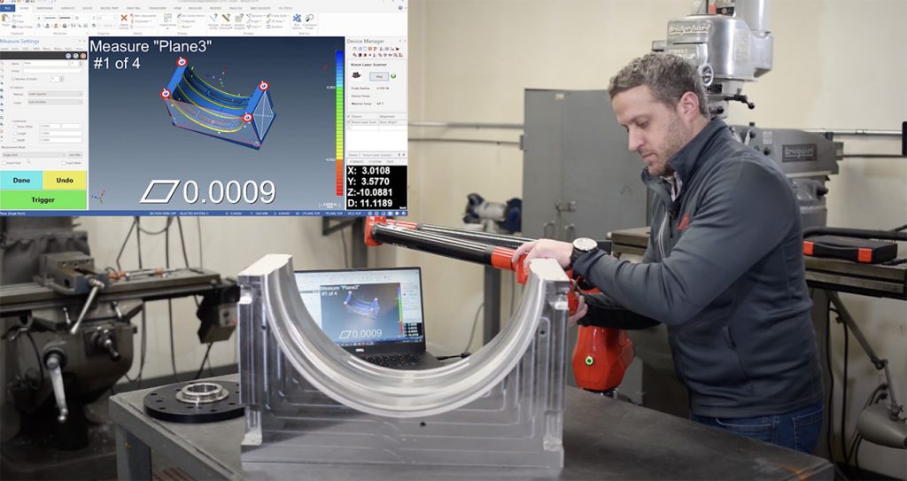
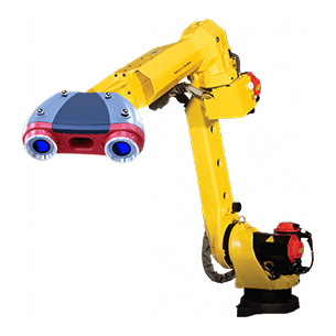
For many manufacturers today, the most common application of 3D laser scanning is for inspecting small parts for Prototype Inspection, Reverse Engineering, CAD comparison, and other quality inspection checks. This scanning work is usually performed on pieces smaller than a few meters in length or diameter. And, fortunately for quality inspectors, there are several tools that can perform these kinds of checks, from hand-held scanners to multi-axis arms. The key for these inspections is accuracy, which is why the equipment that is best for small part inspection work typically uses Triangulation to produce the most accurate data.
Triangulation for 3D laser scanning is a process where the laser emitter, the laser point on the inspected part, and the scanner’s high definition camera make up the three points of a triangle. The software uses the known quantities of the distance between the laser emitter and camera and the angle at the laser emitter’s corner and calculates the camera’s angle to the laser point to discern the rest of the information about the triangle. This allows the distance between laser emitter and laser point and the angle of the point to the camera to be analyzed.
The laser’s beam contains hundreds of thousands of these points that are moved across the part every second, and the software records the changes in distance and angle to repeatedly calculate those triangle values for each point and create useable surface information in a working computer model. This virtual model of the part can be used for CAD comparison, part or mold validation, reverse engineering of a new CAD model, and more.
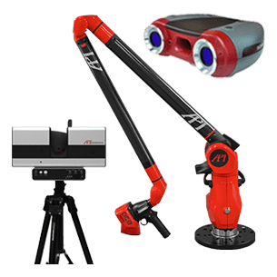
The hand-held and arm scanners used for this inspection work have the freedom to move around the part to scan features from different angles and elevations to get the most complete and accurate digital model possible. In order to move, however, the scanners must be tied to some kind of reference point, namely photogrammetry stickers or an external tracker (like encoders mounted in the arm base or an outside Laser Tracker acting as the point of origin in the coordinate plane).
Large Part Inspection Work
Many manufacturing projects, particularly in Aerospace, Transportation, and Energy, produce parts much larger than a few meters. These parts, however, often still require scanning to verify the CAD model and production and assembly processes, which creates a more difficult setup. They are too large to be done comfortably with a hand-held scanner and photogrammetry stickers (although the process can be painstakingly done), but they still require the accuracy of triangulation over time-of-flight scanning (which we cover in the next section).
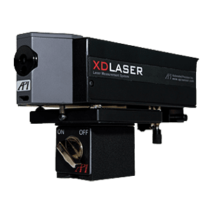
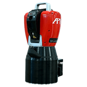
The best solution for these inspections is to take the external tracking method of small part inspections and scale it up to match the project. While this is still generally too much for the encoders in a multi-axis arm alone, Laser Trackers have been used for inspections of airplane wings, windmill rotors, and aircraft carrier assembly for decades. Laser Trackers can easily handle the working range of assemblies up to 80m and can use tie-in points to move that range around the circumference of large assemblies.
Using the tracker as a stable point of origin, hand-held and arm scanners once again have the freedom to accurately triangulate the fine details and features of a machined part, while the tracker and third-party software stitch together the various scanning orientations and locations to produce one large point-cloud mesh of the entire scan data.
Large Space Information Modeling
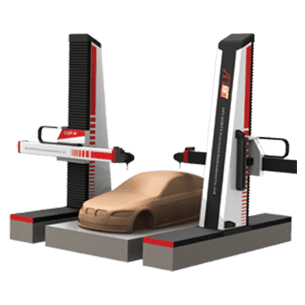
Beyond machined parts and assemblies, scanning has become very useful for creating large digital environments of buildings for factory planning, land surveying and construction planning, and preservation of historical landmarks. And even with the aid of a Laser Tracker to expand the scanning range, these scans are far too time-consuming to perform with a hand-held or arm scanner. Yet, while these scans still require accuracy, the requirements are closer to millimeters as opposed to microns (which triangulation offers).
The lower accuracy requirements allow for the use of time-of-flight scanners for applications of this size, which can scan more quickly and at greater distances than triangulation scanners. Time-of-flight scanners calculate distance by timing how long it takes after the laser emitter sends out a point for it to become visible against the wall or target it is scanning. This distance is calculated over tens or hundreds of thousands of points a second to create a point-cloud of the scanned surface.
Time-of-flight scanners are typically mounted to a tripod or stable fixture, so they can act as their own point of origin, rotating on that point or using mirrors to scan the entire room in a single setup or stitching together a few setups for locations that have interrupted layouts.
In short, while 3D Scanning is often used as a comprehensive term, it actually represents several different types of equipment and best practices, only one of which may be right for your manufacturing application. The easiest way to begin focusing the list of options is to consider the scale of your needed scan work and the tolerances required. This will help determine whether time-of-flight, triangulation, or external tracking will be needed for your work. If you need further help determining the right scanning solution for you, contacting a Metrology Service Provider (MSP), like API Services, for a consultation or contracted scanning work provides an expert opinion to help you determine what solution best fits your needs.