

In our “What is Calibration?” article, we discussed how calibration is a two-step process of first evaluating equipment performance against a reference standard and second using that information to improve equipment performance. And we looked at how many of the “Calibration” services offered for Laser Trackers are actually mislabeled, as they don’t perform the second step. But what happens when we apply these same standards to Machine Tools? How do the calibration products and services that are available actually identify and correct errors in machine tool performance, and do they meet both criteria for calibration as defined by the VIM?
Machine tools are the lifeblood of industrial manufacturing, and they have been for more than two centuries. Regardless of industry, every major engineering project at some point requires a large piece of material be shaped through some combination of cutting, grinding, pressing, boring, or drilling. These reshaped pieces may serve as new parts to be installed, housing for other parts in an assembly, or molds that other pieces can be shaped in. And as machine tools have grown more accurate through Computer Numerical Control (CNC) and Computer Aided Design (CAD), the parts designed for them have developed more intricate features across larger scales with tighter tolerances.
It is more important than ever for manufacturers that their machine tools are not only accurate at the outset, but that they remain accurate over time, so as to avoid costly rework and scrap. In order to ensure machine tools around the world are operating at their optimal accuracy, the International Organization for Standardization (ISO) and the American Society of Mechanical Engineers (ASME) updated their definitions and standards for Machine Tool Calibration (MTC) measurements in the early 2000s.
What is Machine Tool Calibration?
Traditionally, calibration measurements only looked for Displacement errors, which were found by measuring the linear movement along each of the three axis of the machine tool (X, Y, and Z). Finding and correcting these three sources of error was typically enough to keep a machine tool within tolerance.
But as tolerance demands have grown tighter on newer, more intricate models, new standards like ISO 230-6 and ASME B5.54 have identified many other sources of error that need to be taken into account for machine tools to maintain their highest level of performance. In addition to the three Displacement errors we noted earlier, these new standards highlight 18 other error parameters that must be taken into account in calibration measurements. So, our standard 3-axis machine tool now has 21 possible errors to calibrate.
Where are the Errors?
Now, 21 sounds like a lot of errors, but we can actually group them together pretty simply into axial or squareness groups. Each axis of the tool has the same 6 possible errors as it moves through its path. The first is Linear Positioning, which old standards measured for in the past, but as that axis moves, we must also look for Vertical and Horizontal Straightness and identify any Pitch, Yaw, or Roll movements. Those 6 errors are found on each axis, which makes up 18 out of 21. The final 3 errors are in the machine itself, as it must be square at the XY, YZ, and XZ junctions.
Many MTC products and service providers still only measure Displacement errors and could be missing as many as 18 other issues with your machine, so it is important when researching calibration methods to ask how many error parameters will be found and compensated for.
Does MTC Meet VIM-defined Standards?
Going back to the VIM definition of calibration, compensation is that second piece that is needed to actually improve machine performance. For MTC, compensation is actually the simpler step. Once all of the measurements have been taken to establish where errors are taking place, the metrology software is able to create a compensation table report that is uploaded directly to machine tool controller to instantly improve performance.
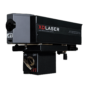
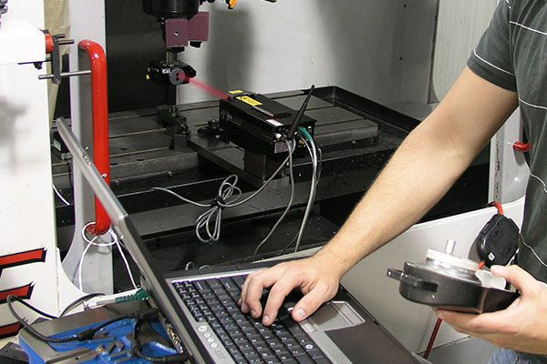
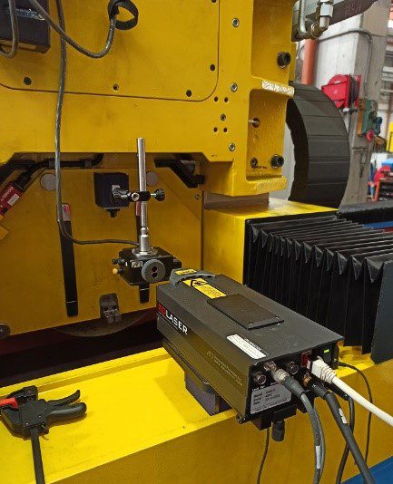
In short, machine tools have fueled every industrial revolution, and as their performance has improved, the designs and demands made on them have increased. To keep machine tools running at their highest capacity, calibration standards have changed, requiring equipment and service providers to examine all 21 possible error parameters for a 3-axis machine. API’s XD Laser is capable of measuring and correcting for all 21 errors in a single, easy setup, and our Globally-Local Services team has decades of experience calibrating more than 20 types of machine controller. To learn more about MTC, please visit apimetrology.com and contact us to speak to a Real Metrologist today.

Sources:
