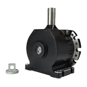
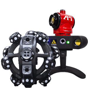
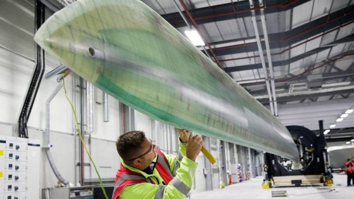
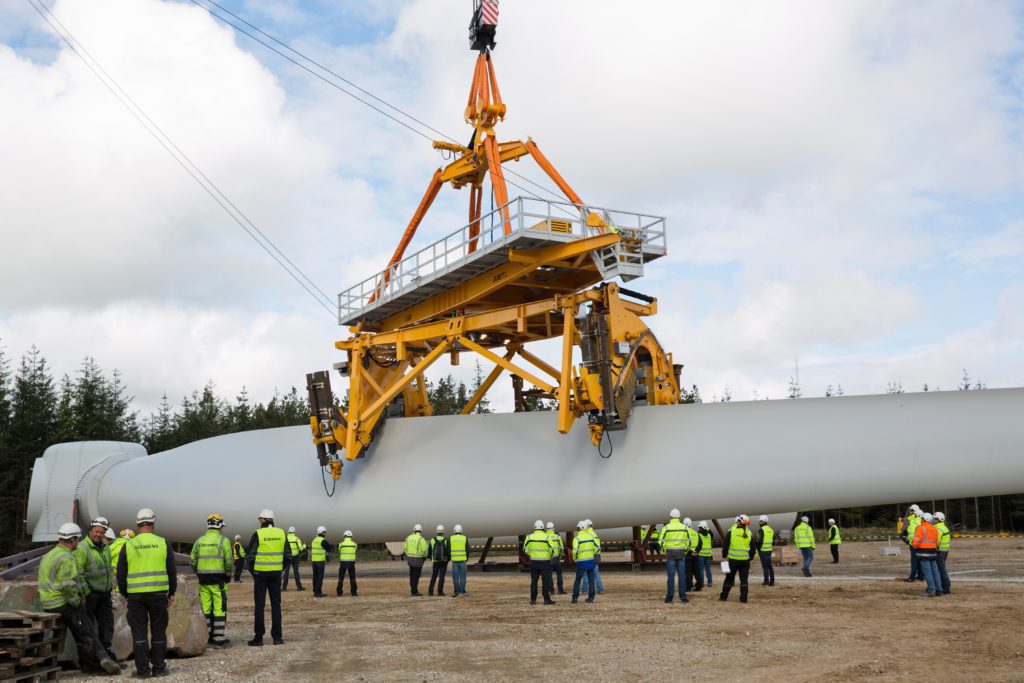
The rotor blades used on windmills to harvest the power of wind are far more complex than they appear from the ground. The blades are intricately designed yet molded and assembled on a grand scale. In fact, some of these blades are so large, they cannot be transported by road. They must be machined and welded at costal locations and then taken by ship directly to their installation spot in the sea. Even at these on-location sites, however, the tolerance at the tips of these blades is a single millimeter. This combination of precise design and large mass makes portable metrology equipment a must for the production of these blades.
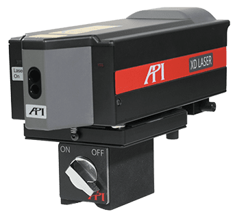
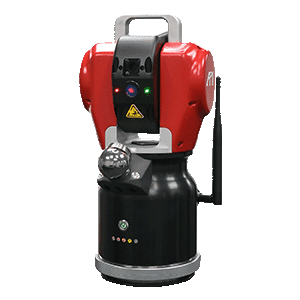
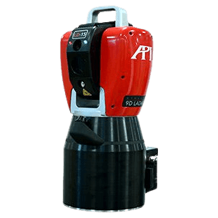
While in the past, theodolites and template comparisons were used for determining accuracy in large fabrication projects, Laser Trackers have become the standard in these industries (like Shipbuilding and Aerospace). Far from being different, the use of Laser Trackers might be even more essential to the wind power industry. There is a higher level of uncertainty in the molding process for these rotor blades. Any faults in the mold are doubled during casting and again during manufacturing because the blade is wet during construction. Therefore, the potential shrinkage must be accounted for as the blade dries.
From verifying and leveling the molds to part verification and alignment to managing “Smart” inspection systems, Laser Trackers are now embedded in almost every stage of the rotor blade production process. Below are some of the most important uses of the Laser Tracker in this field:


Mold Leveling
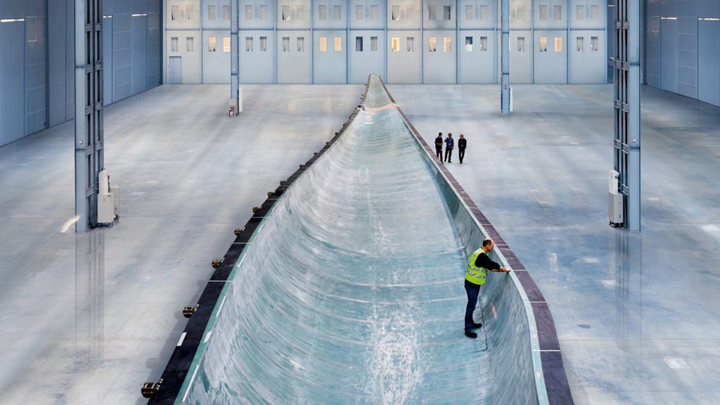
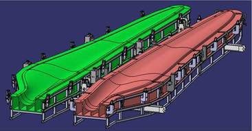
The greatest way to ensure accuracy in the finished rotor is to ensure the accuracy of the mold it is casted from. The level of the mold, and the spandrel braces holding its position, is verified by Laser Tracker measurements repeatedly before and during casting. As blade designs have become increasingly longer and thinner to maximize wind capture, the complete measuring range of the Laser Tracker has become more essential. The Tracker is also used to compare the casted rotor to the mold itself, allowing for mold adjustments to be made between castings. This comparison also makes it easier to manage the “Spring In” effect of oval molds needing to produce round blades.
Parallel Cross Section Cuts
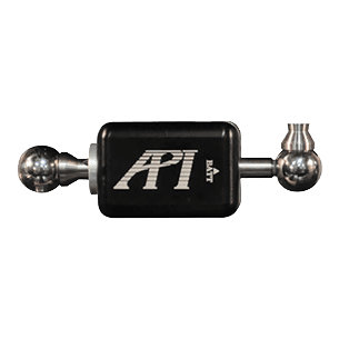
After casting, parallel cross section cuts are made on the rotor blade. Ideally these cuts are matched to reference notches that show cut locations from the mold. These reference notches need to have their locations confirmed by Laser Tracker measurement, especially for larger offshore rotors. The Laser Tracker with target mounted on an extendable rod is ideally suited for these dynamic scanning measurements.
Template/CAD Verification
Previously, casted rotor blades were taken to a template model blade for direct comparison. While accurate, this process was time consuming and became unwieldy once offshore blade depths exceeded 5 meters. Using a Laser Tracker, blade manufacturers are now able to bring the template data to the rotor. They can use the Laser Tracker’s measurements to compare the casted part directly to the CAD model to ensure accuracy without having to move the rotor, saving time, effort, and cost.
Drill Set-Up and Positioning
After casting and initial inspection, drills are set up on the rotor blade to bore bolt holes into the blade root. These holes are used to attach the blade to the windmill base. The drills must be positioned to place the bolt holes in extremely precise locations to ensure secure mounting with force capture of the blade for efficient performance. Laser Trackers are used to verify the drill’s position and to monitor the blade’s position for shifting during the drill process.
Scanner Positioning
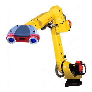
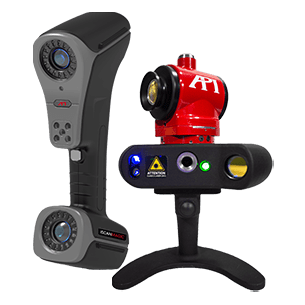
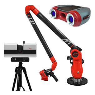
Automated inspection systems (like API’s RapidScan) can be set-up to scan the entire surface of a casted rotor blade. Laser Trackers are essential for the positioning and data plotting for these scanners. As the scanner changes position or orientation to capture the entirety of the blade, the Laser Tracker acts as a point of origin for the scanner and is able to stitch the various data planes captured by the scanner into a single point could that can be used for CAD comparison or modeling.
3D Deflection and Center-of-Gravity in Load Bearing Testing
Assembled rotor blades undergo extensive load bearing capacity tests. The blade is deflected with cranes at various points, with the forces measured. A Laser Tracker measures the 3D deflection. Dynamic oscillation evaluations are also possible. The twisted rotor blade shows linked oscillations and oscillates ovally. The structural angles are calculated via the axis of the principal stiffnesses. This data is also used to calculate the center of gravity. The center of gravity for all blades of a set must match very precisely.
Other Windmill Measurements
While the rotor blades are the most specialized piece of the windmill, the rest of the production and assembly calls for equally tight tolerances. Laser Trackers are used for all of these processes. Each machined part for the tower has its part geometry and hole positioning verified to CAD data by Laser Tracker measurements. The position, assembly, and alignments of the tower are also verified on-site, making the portability of the Laser Tracker a must. This includes using the Tracker to find component positions inside the tower and controlling the drilling position on the assembly surfaces.
Throughout every stage of the casting and inspection processes for rotor blades and for the verification and assembly of the windmill tower, the portability and accuracy of Laser Trackers saves cost, time, and effort, while allowing for longer, thinner blade designs that can capture the maximum amount of wind possible. To learn more about API’s Radian Laser Tracker Series, click here.
Want to learn more about how API can help you with Wind Energy? Fill out the form below to talk to one of our expert Metrologists.


