
Machine tool guideway straightness measurement is one of those checks that quietly decides whether a machine can still hold tolerance five years after installation. When the guideway drifts out of straight, the error doesn’t stay on the rail. It shows up in positioning, cut quality, repeatability, and the parts that come off the machine. The straightness check is small. The downstream impact is not.
This article walks through the three methods machine builders and service technicians actually use, what each one is good at, where each one slows the job down, and why a position-sensing laser interferometer like the API XD Laser-3D has changed how installation and adjustment work gets done.
Why guideway straightness determines machine tool performance
A guideway is the rail a moving carriage rides along. Spindle housings, tool turrets, work tables, gantry beams — anything that has to travel in a controlled line sits on a guideway of some sort. If that rail isn’t straight, the controlled line isn’t straight either, and every cut the machine makes carries that error.
What “straightness” actually means in a guideway context
Straightness in this context is the deviation of the carriage’s actual path from a perfectly straight reference, measured in two planes: vertical (up-down relative to the axis of motion) and horizontal (side-to-side). Both matter. A guideway can be flat in one plane and sagging in the other, and a single-plane check will pass it while parts come off the machine out of square.
This is also where guideway straightness departs from generic GD&T straightness. A coordinate measuring machine can check the straightness of a finished part by walking a stylus along an edge. A guideway is different. You are measuring the path a moving mass actually takes under its own bearings, sometimes over five or six meters of travel, in two planes at once. The toolset is different too.
The downstream cost of an out-of-tolerance guideway
When a guideway is off by even ten or twenty micrometers over its working length, the symptoms show up in places that can be hard to trace back. Hole positions creep out of pattern across a workpiece. Surface finish degrades on long passes. Tools wear unevenly because the cutting load isn’t distributed the way the toolpath assumed. Repeatability drifts and the operator starts blaming the program when the rail is the problem.
That is why straightness gets checked at three points in a machine’s life: at original installation, after any service or crash recovery, and on a recalibration schedule (ISO 230-1 recommends annual checks for production CNC equipment). If straightness is wrong at any of those moments, every other geometric correction the machine carries is built on a weak foundation.
How do you measure straightness of a machine tool guideway?
You measure it by comparing the carriage’s actual path against a known straight reference. The reference can be a physical edge, a beam of collimated light, or the path of a laser interferometer. The method you pick comes down to guideway length, accuracy target, and whether you need to adjust the machine in real time while you measure.
The three accepted methods
The three methods, in order of how long they have been around:
- Straightedge with a dial indicator. Physical reference, mechanical readout. Suits short guideways and quick field checks.
- Autocollimator. Measures angular tilt at points along the axis, then mathematically reconstructs the straightness profile. Longer reach than a straightedge, but slower.
- Laser interferometer with a position-sensing detector. Measures both straightness planes directly during the same pass that captures positioning, repeatability, and backlash. Faster and easier to use across the working length.
Each method has a role. The straightedge is still the right call for a quick check on a one-meter axis. The laser interferometer wins on anything longer, anywhere accuracy matters, or anywhere you need to adjust the machine while you measure.
What is the ISO standard for guideway straightness?
Two standards apply, and machine teams often confuse them.
ISO 2768-2 sets general geometric tolerances for finished components — the catch-all spec for parts where the drawing doesn’t specify tighter limits. It applies to the manufactured rail itself, not to its performance on the machine.
ISO 230-1 is the machine-tool-specific standard. It defines the geometric accuracy tests for axes of motion, including how straightness of a linear axis should be measured in both the vertical and horizontal planes, and the conditions under which the test is valid. When a builder ships a machine with a straightness specification, that specification is almost always written against ISO 230-1.
For most calibration work, ISO 230-1 is the document on the bench.
Method 1: Straightedge and dial indicator
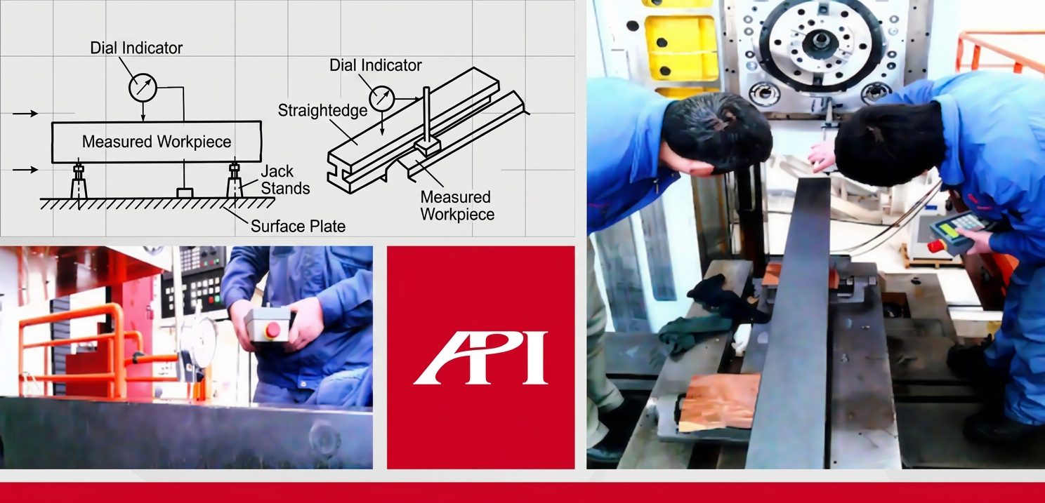
The straightedge method has been around as long as machine tools have. A precision-ground steel or granite straightedge gets clamped along the axis, a dial indicator rides the surface, and the operator reads the deviation at each station along the travel.
Setup and procedure
The straightedge gets supported at its Airy points (the spacing that minimizes its own sag), the indicator is zeroed at one end, and readings are taken at fixed intervals along the length. The numbers get plotted as a deviation curve. The peak-to-valley value is the straightness error.
For one-plane checks on short guideways — say a meter or less — the method is honest, low-cost, and traceable. We still recommend it as a sanity check on small precision lathes and toolroom mills.
Where this method falls short on long guideways
The trouble starts when the guideway gets longer than the straightedge. A two-meter granite straightedge weighs north of 100 kilograms and is a project to move. A four-meter axis can’t be covered in a single setup at all, so the straightedge has to be repositioned and the readings stitched together, which introduces its own error.
There is also the operator factor. A dial indicator reading depends on how the operator lands it, how square the indicator tip is, and how the operator interprets a needle that doesn’t quite stop moving. Two technicians measuring the same axis with the same equipment will get readings that differ by a few micrometers, which is meaningful when the tolerance is ten or twenty micrometers across the full length.
Bulky, slow, subjective. The straightedge keeps its place on short axes, but the moment a guideway gets long, machine teams reach for something else.
Method 2: Autocollimator
An autocollimator measures small angular deviations of a reflective target. On a guideway, a mirror is mounted on the carriage, the autocollimator stays fixed at one end of the axis, and as the carriage moves, the angular tilt of the mirror is recorded at intervals along the travel. Those angular readings get integrated mathematically to produce the straightness deviation curve.
How autocollimator straightness measurement works
The math is straightforward. If you know the angular tilt at each station and the spacing between stations, you can reconstruct the path the carriage took. The autocollimator does not measure deviation directly — it measures slope, and the operator (or the software) converts slope into deviation through the integration step.
That conversion is where the method’s character shows. The longer the axis, the more stations you measure, and the more accumulated error you can collect from the integration. Modern digital autocollimators handle this well on a settled machine. They are also fully optical, so there is no contact pressure to disturb the carriage.
Strengths and limitations
An autocollimator goes further than a straightedge, takes up less floor space, and gives a cleaner digital readout. For pure straightness work on a stable, fully assembled machine, it’s a sound choice and many calibration labs still use one.
The limitations matter when the job is more than just collecting numbers. An autocollimator does not naturally tell the operator what to do next. The data comes off the instrument as an angular trace, and the operator has to translate that into a real-time adjustment of the machine — usually by shutting down, making a correction, running the measurement again, and seeing whether the trace improved. On a service call where the goal is to bring a machine back into spec quickly, that loop is expensive.
The autocollimator also commits the operator to a separate setup for any other parameter — positioning accuracy, repeatability, backlash. Each of those checks is its own job with its own instrument. That fragmentation is what the next method removes.
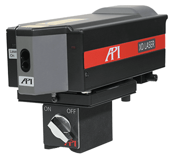
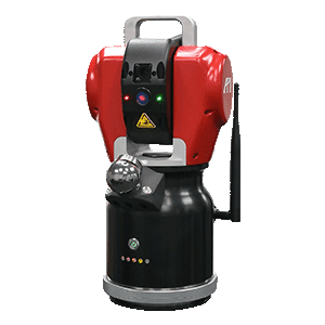
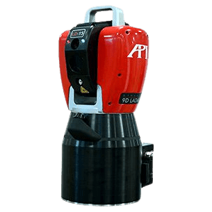
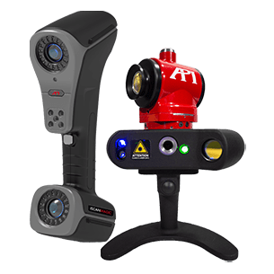
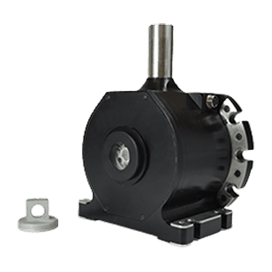
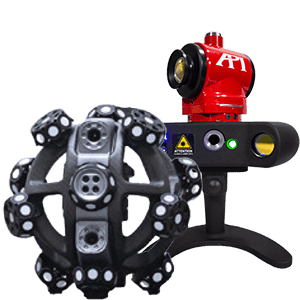
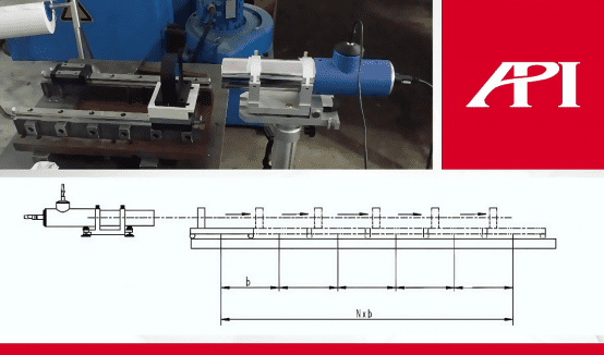
Method 3: Laser interferometer straightness measurement (XD Laser-3D)
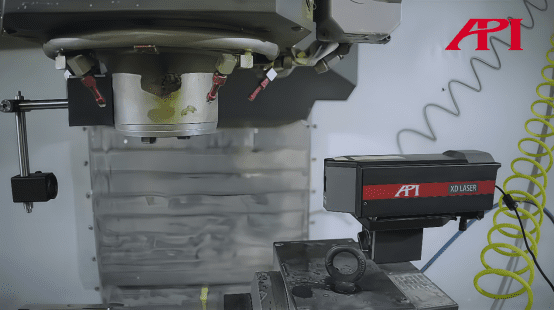
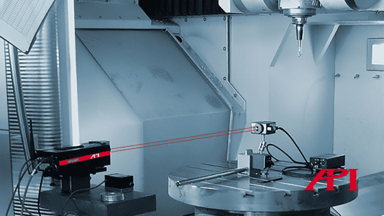
A laser interferometer is the modern standard for machine tool calibration. A laser source establishes a reference beam, a retroreflector mounted on the carriage returns the beam, and the interferometer measures the change in optical path length as the carriage moves. That measurement gives positioning accuracy to roughly 0.5 micrometers per meter of travel, which is at least an order of magnitude better than mechanical methods.
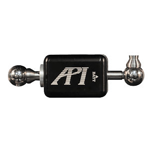
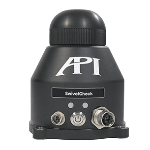
The API XD Laser-3D takes the laser interferometer further by integrating a position-sensing detector (PSD) into the reflector itself. That changes what the system can capture in a single setup.
How the PSD-equipped interferometer captures straightness in one setup
A standard linear laser interferometer measures only along the axis of the beam. It tells you how far the carriage traveled, and nothing else. The PSD inside the XD Laser-3D’s reflector adds a second function. As the carriage rides along the guideway, any deviation from a perfectly straight path shifts the beam’s landing position on the detector. That shift is captured as a real-time straightness reading.
The result: positioning data and straightness data come off the same pass. The optical components do not change between the two measurements. That alone removes a setup cycle that older methods treat as two separate jobs.
Vertical and horizontal straightness from a single pass
The PSD is two-axis. As the carriage moves, vertical straightness (up-down deviation relative to the axis of motion) and horizontal straightness (side-to-side deviation) are recorded simultaneously. ISO 230-1 wants both planes for a complete straightness specification, and the XD Laser-3D delivers both without rotating the optics or repositioning the sensor.
For longer guideways this matters more, not less. On a six-meter gantry axis, the conventional approach is two passes for straightness, plus a third for positioning. The XD Laser-3D collects all three in one pass. The time savings show up immediately on installation work, where a builder is calibrating a dozen axes back to back.
Real-time straightness observation during machine adjustment
Setup the system, set two reference points at the start and end of the guideway, zero the straightness data, and the operator watches live values on the controller as adjustments are made on the machine. That last detail is the part field technicians notice first.
Straightness inspection rarely exists for its own sake. On a service call, the report matters less than getting the machine back into tolerance before the next production shift. The real-time observation function turns the measurement into a guidance tool. You adjust the rail mounting or the bearing preload while watching the straightness number move, and you stop when the value is inside spec. That feedback loop is what neither a straightedge nor an autocollimator gives you directly.
Straightedge vs autocollimator vs laser interferometer
A side-by-side view of the three methods on the parameters that actually decide which one to use.
| Criterion | Straightedge + indicator | Autocollimator | XD Laser-3D |
|---|---|---|---|
| — | — | — | — |
| Practical guideway length | Up to ~1 m | Up to ~30 m | Up to ~80 m |
| Accuracy (typical) | 5–10 µm/m | 1–2 µm/m | <1 µm/m |
| Vertical + horizontal in one pass | No | No (sequential) | Yes |
| Captures positioning, repeatability, backlash | No | No | Yes (same setup) |
| Real-time adjustment feedback | Manual reading | Indirect | Yes |
| Operator skill dependency | High | Medium | Low |
| Setup time on a 5 m axis | 30–60 min | 20–40 min | 10–15 min |
| Best fit | Short toolroom axes, field sanity checks | Stable, fully assembled machines, lab work | Installation, service, recalibration on production CNC |
The fastest method is not always the right method. A toolroom lathe gets checked with a straightedge because the operator already has one and the axis is a meter long. A heavy-machinery installer reaches for the laser interferometer because the next axis is twelve meters and the schedule is tight. Match the tool to the job.
What tool is used to measure straightness?
Three tools, depending on the situation:
- A precision straightedge with a dial indicator for short axes and quick field checks where the tolerance is loose.
- An autocollimator for medium-length axes on a stable machine where the team has time to run a full optical setup.
- A laser interferometer with a position-sensing detector (the XD Laser-3D) for anything where guideway length, accuracy, or adjustment speed matters. This is the modern default on CNC machine tools.
A coordinate measuring machine can measure straightness of a finished part, but it is the wrong tool for a guideway, because the guideway is the path of a moving mass under load, not the geometry of a static workpiece.
Beyond straightness: other parameters the XD Laser captures in one setup
The reason machine teams switch to the XD Laser is rarely straightness alone. It is what comes with straightness in the same setup.
Positioning accuracy, repeatability, and backlash
A linear axis is specified by more than its straightness. Positioning accuracy is how close the commanded position matches the actual position. Repeatability is how consistently the axis returns to the same commanded position across multiple approaches. Backlash is the lost motion when the axis reverses direction.
All three are captured by the XD Laser-3D during the same run that measures straightness. The operator does not change optics, does not change the reflector, does not rerun the program. One axis, one setup, four parameters out the other side.
For installation work this matters because the parameters interact. A guideway that is straight but loose on repeatability points to bearing preload. A guideway that repeats well but reads positioning error points to ballscrew compensation. Measuring them together makes the diagnosis obvious.
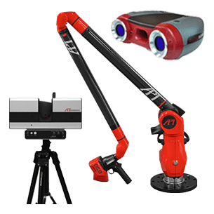
Scaling up: XD-6D for X, Y, Z, yaw, pitch, and roll
The XD Laser-3D handles linear axes. The XD-6D in the same product family measures six parameters at once on the same axis: linear position, two straightness directions, and three rotational errors (yaw, pitch, and roll). On a five-axis machining center, that compresses what used to be six separate setups into one. API has measured this in the field at roughly five times the inspection efficiency of a conventional interferometer workflow.
The 6D capability is what turns the XD Laser line from a calibration instrument into a machine-performance platform. The same family of optics fits installation, service, recalibration, and certification work.
When to recalibrate: installation, service, and periodic checks
Three moments call for a straightness check.
The first is installation. Every new machine arrives with shipping settled into its bearings and mounting feet. Straightness gets verified before the machine accepts its first production part. This is the moment the laser interferometer pays for itself fastest, because the builder is moving from axis to axis on a tight schedule and any setup time saved compounds.
The second is service or crash recovery. A spindle collision or a hard stop can move a guideway by tens of micrometers. After any incident severe enough to trigger an error, straightness goes back on the list before the machine returns to production. Real-time adjustment feedback matters here more than at any other moment. The goal is to bring the machine back into spec quickly, not just to document where it landed.
The third is periodic recalibration. ISO 230-1 recommends annual checks for production CNC. For high-precision work or for machines running three shifts, more frequent checks make sense. Many API customers pair the XD Laser-3D inspection with an ISO 17025 accredited calibration certificate for traceability.
If your maintenance calendar does not currently include straightness as a documented periodic check, that is the first thing to put on it. The cost of catching drift early is far below the cost of scrapping parts because nobody saw the rail moving.
Frequently asked questions
How do you measure straightness?
Straightness is measured by comparing the path of a feature against a known straight reference. On machine tools, three methods are accepted: a straightedge with a dial indicator for short guideways, an autocollimator that measures angular deviation along the axis, and a laser interferometer with a position-sensing detector that captures straightness in both vertical and horizontal planes in a single pass.
How do you check a shaft for straightness?
A shaft is checked by mounting it between centers or on vee blocks and rotating it against a dial indicator. The total indicated runout reads the deviation. For higher accuracy or longer shafts, a laser-based system measures the centerline directly without the contact pressure that can mislead a dial indicator.
What is the ISO standard for straightness?
General straightness tolerances for finished parts fall under ISO 2768-2. For machine tools specifically, ISO 230-1 defines the geometric accuracy tests for axes of motion, including straightness of linear axes in both vertical and horizontal planes.
How accurate is a laser interferometer for guideway measurement?
A modern laser interferometer measures linear positioning to roughly 0.5 micrometers per meter of travel. With an integrated position-sensing detector, the straightness channel typically resolves to about 1 micrometer over standard guideway lengths, well inside the tolerances most machine tool builders work to.
Can the XD Laser-3D replace an autocollimator?
For most machine tool installation and adjustment work, yes. The XD Laser-3D captures the same vertical and horizontal straightness data an autocollimator provides, while also measuring positioning, repeatability, and backlash in the same setup. Autocollimators still have niche uses in optical alignment, but on a machine tool axis the laser interferometer covers the work faster.

Next step: Talk to an API metrologist
If you are planning an installation, recovering a machine after service, or putting together a recalibration schedule, an API metrologist can help you scope the right approach for your axes and your tolerance targets. Reach out through the contact page, or learn more about the XD Laser-3D laser interferometer directly.