
API Arm Reverse Engineers Cast Aluminum Part
Articulating Arm with Scanner Showcases API Services’ Simple, 4 Step Process
Non-contact, 3D laser scanning and reverse engineering have become some of the most sought-after applications for productions of all scales around the world. The proliferation of hand-held and articulating arm scanners that can take tens or hundreds of thousands of points per second has dramatically improved the speed with which a CAD model can be created or updated based on an existing part. And these improvements have greatly expanded business’ ability to alter current product designs and bring legacy parts back into production, both by owning and operating their own scanning equipment and software or by contracting a Metrology Service Provider (MSP) to perform the scan and modeling for them. And when a customer sent a part to API Services with just that request, the team was able to deliver results using their simple, 4-step procedure of:
- Performing a complete scan of the part with API Arm and Skyline Scanner
- Generating a 3D model and incorporating design changes
- Using false color comparison to verify the new model
- 3D printing a new prototype for shoring and evaluation
Across all industries, objects with free-form surfaces are increasingly becoming the subjects of reverse engineering projects. These free-form surfaces are commonly found in automotive engineering for car bodies, primary and forming technology, and in the energy machine sector for turbine and compressor blades. This reverse engineering process involves: the digitization of objects from the design area of automotive engineering or manually created design studies which are to be made accessible for further computer-aided processing, e.g. manufacturing, flow, or FEM simulation.
Nowadays, design complexities and embellishments are being added to projects as they are developed or as updates after they have already been in production for some time. And, in these cases, reverse engineering can save a lot of time and money in development. The creation of a 3D model of any object, can be solved with the API Arm quickly, accurately, and cost-effectively. The experienced team of globally-local Real Metrologists at API Services were able to deliver this benefit to a customer who needed rapid reverse engineering of a cast aluminum part using the simple 4-step process shown below
The goal of reverse engineering is to enable accurate redesign of a product when CAD data or drawings are no longer available. This approach is often combined with the integration of improvements to existing design elements. This is where design engineers often reach their limits when using conventional measurement methods. In particular, the measurement of complex contours and free-form surfaces is often difficult.
Step One: Scanning with API Arm
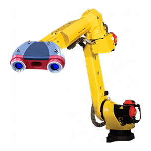
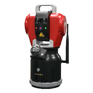
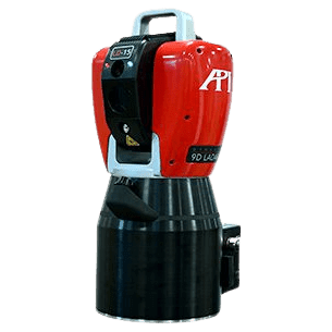
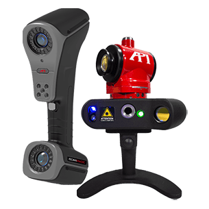
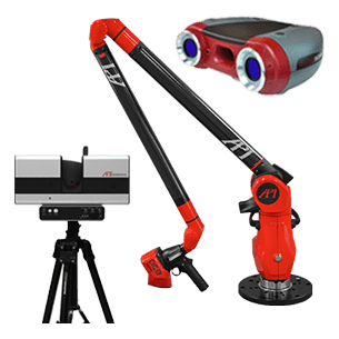
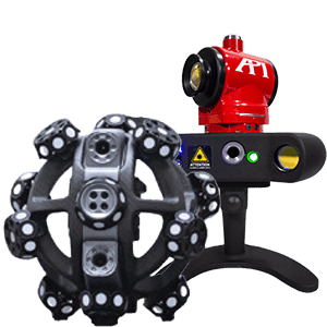
To reverse engineer this cast aluminum part, API metrologists used the API Arm in conjunction with the ACE SKYLINE WIDE laser scanner to scan the surface of the casting and create a polygon model.
The API Arm and WIDE scanner can pick up 600,000 points per second at an accuracy of ∓ 15 μm, so the scan could be performed quickly and with high precision.
Step Two: 3D model generation
Once the scan was complete, the API Services engineers then used metrology software and the created point mesh cloud to make a 3D model based on the polygon model and immediately incorporated the customer’s change requests. In this case, the wall thickness was influenced, and the bore diameter was adjusted.
Step Three: Verification of the result
Once the scan and the new CAD model have been completed, the new design needs to be verified, which makes up Steps Three and Four of this process. To verify the result before production, a false color comparison of the new CAD model with the polygon model was then made to identify any unintended deviations. Once the new CAD model was verified, it could be subjected to a test production in Step Four.
Step Four: Creation of a physical model
Following the color comparison, a physical model was created by API Services in a 3D printer in order to evaluate the physical results, as well as the virtual and data results. By performing this step, the customer received their first prototype directly and was able to start the first shoring test. This approach is very efficient: it saves an enormous amount of time and money, since no new tools have to be built for the prototype. The customer can then check whether the prototype meets all of their requirements, and, if necessary, adjustments can made again in the CAD model created in Step 2. As soon as everything fits, production implementation can begin.
As Reverse Engineering needs become more commonplace, and the timetables for these projects grow shorter, API Services has adapted and developed a simple process to deliver fast, accurate, testable models to our customers. You can click the links below to learn more our API Arm and our Reverse Engineering Services or fill out the form if you would like to speak to a Real Metrologist today.
Learn more about the API measuring arm: https://apimetrology.com/api-arm/
Learn more about API’s reverse engineering service: https://apimetrology.com/reverse-engineering/
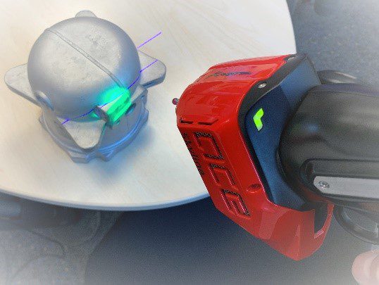
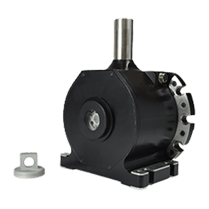
Fig. 1: API Arm scanning the aluminum casting with high precision
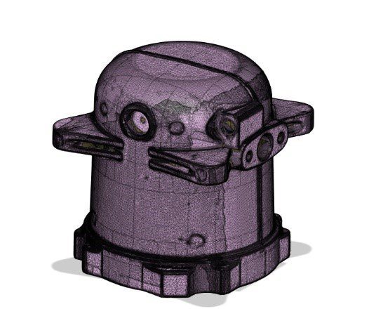
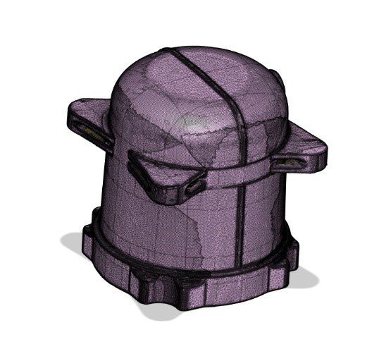
Figs. 2 + 3: Polygon model of the aluminum casting from the front and rear.
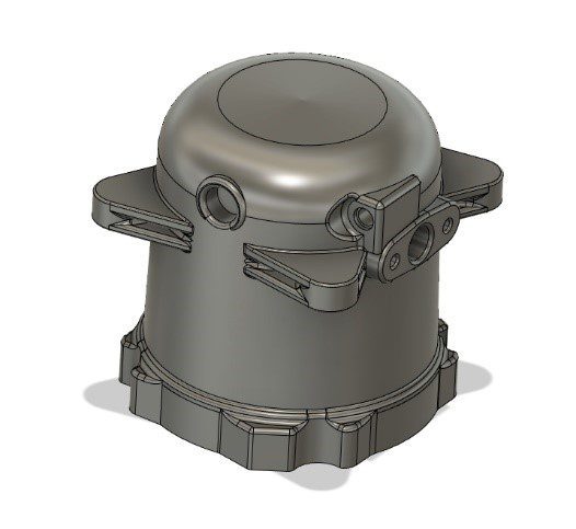
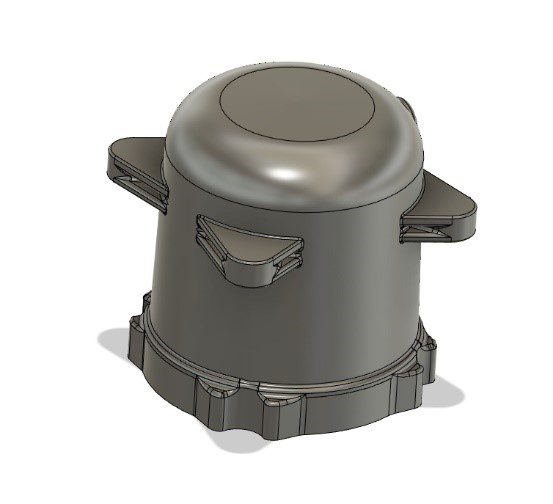
Fig. 4 + 5: CAD model of the cast aluminum part from the front and from the back.
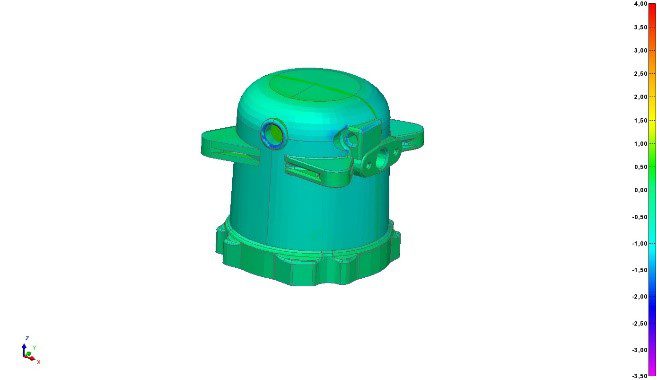
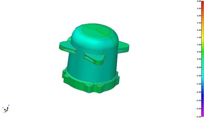
Figs. 6 + 7: False color comparison of the aluminum casting from the front and from behind.
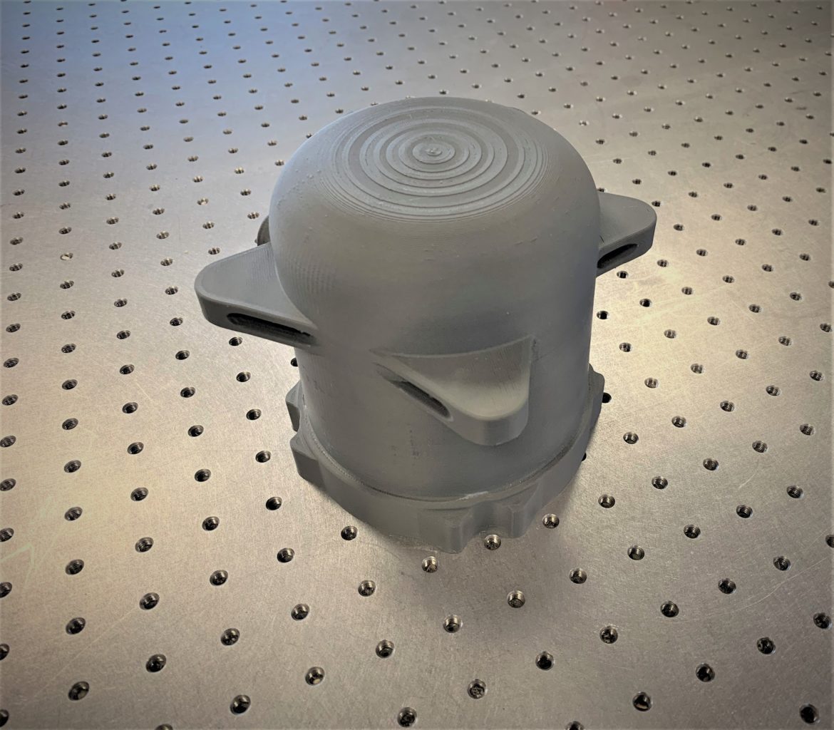
Fig. 8 + 9: Finished 3D print of the aluminum casting from the front and from the back.