Why Lithography Machine Bases Are So Demanding
In semiconductor manufacturing, lithography equipment has almost no tolerance for an unstable foundation. The machine is projecting nanometer-scale circuit patterns onto wafers, and its physical base has to preserve a precise reference geometry while carrying equipment that can weigh several tons.
That makes the base more than a support structure. It is part of the machine’s accuracy chain. A small amount of tilt, settlement, or deformation can become an alignment error in the lithography process, which can reduce yield, compromise performance, or damage sensitive equipment.
For installation teams, the measurement challenge is clear: verify the base surface, hole positions, and relationships between multiple base sections with enough accuracy to support final adjustment and acceptance.
What Has To Be Checked
A lithography machine base inspection typically focuses on three major areas.
The first is base surface levelness. The base surface acts as the zero reference for installation, so it often needs micron-level levelness to help the machine’s guide rails meet their required straightness and levelness.
The second is hole geometry and location. Threaded holes and locating pin holes are used to mount the machine body, vibration isolation equipment, and auxiliary systems. Their diameter, perpendicularity, and 3D position relative to nominal design data need to stay within tolerance. If they do not, installation can become difficult, or mounting stress can be introduced into the system.
The third is the relationship between multiple base sections. Large lithography systems may use separate bases for exposure, measurement, wafer transfer, and other subsystems. During installation, teams need to control spacing, parallelism, height difference, and overall relative position so those separate structures behave as one rigid platform.
Where Traditional Methods Fall Short
Electronic levels, micrometers, theodolites, and CMMs can all play a role in precision measurement, but they are not ideal for this kind of large, high-accuracy installation work.
They can be slow, especially when a large base surface has to be measured point by point. They can also create datum problems when surface levelness and hole-position checks are performed separately. For multi-base adjustment, traditional methods make it hard to see the whole spatial relationship in one coordinate system while adjustments are happening.
The result is often repeated inspection, adjustment, and reinspection. That approach can work, but it adds time and leaves teams with less complete 3D data for analysis, reporting, and traceability.
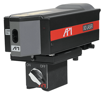
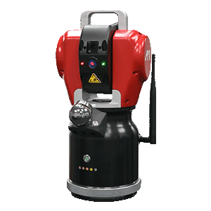
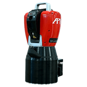
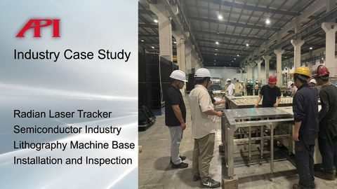
How the Radian Laser Tracker Helps
The API Radian laser tracker gives installation teams a practical way to bring these checks into one global coordinate system. Instead of treating levelness, hole position, and base-to-base alignment as separate tasks, the tracker allows them to be measured and analyzed against the same reference.
That matters because lithography machine bases are large, but their tolerances are tight. The Radian series provides micron-level spatial measurement accuracy, a measurement radius greater than 80 meters, and data collection rates up to 1000 Hz. That combination lets teams cover the base area, capture the geometry quickly, and maintain the accuracy needed across long distances.
The bigger workflow benefit is real-time feedback. During adjustment, the tracker can show the difference between the measured point and the theoretical position while the operator is still moving the component. Instead of measuring, adjusting, and checking again later, the team can guide the adjustment live.
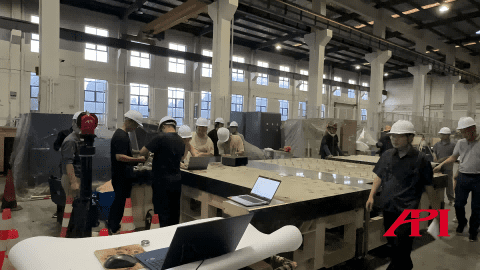
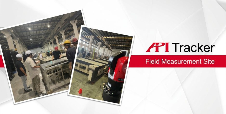
The Inspection Workflow
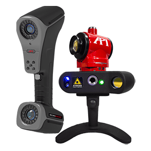
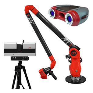
The Radian laser tracker is set up on a stable foundation or tripod at the installation site with line of sight to the base sections and measurement points. From there, the team establishes the initial coordinate system for the inspection.
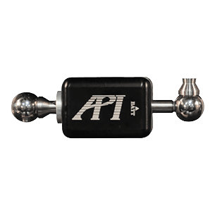
An operator then uses a high-precision SMR target to collect points on the base. The tracker follows the center of the target in real time and sends 3D coordinate data to the measurement software. For surface levelness, the operator can plan a measurement path across the base surface and collect continuous point data. For hole inspection, the SMR is placed in a special pin seat so the hole wall can be measured and fitted for position and size.
That gives the team the data needed to evaluate hole center coordinates, hole diameter, circumference, and position error for critical locating pin holes and threaded holes.
Turning Measurement Data Into Decisions
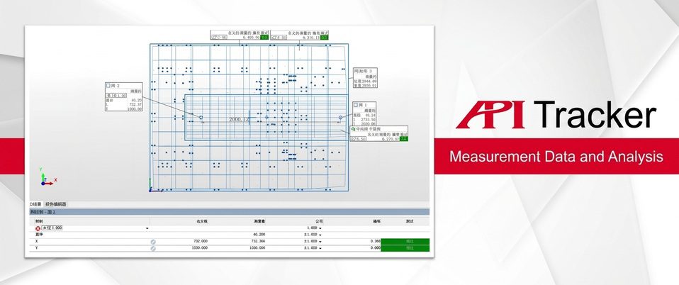
Once the data is in software such as SpatialAnalyzer, PolyWorks, Verisurf, Metrolog, or MeasurePro, the team can analyze everything in the same coordinate system.
For the base surface, the software fits the measured points to a plane and generates a contour view showing flatness error, high areas, and low areas. For hole position, the software fits the measured geometry and calculates X, Y, and Z deviations for each feature. Results can be reviewed in tables or visual color maps so out-of-tolerance features stand out quickly.
That same data also supports formal reporting. Levelness analysis, hole-position deviation lists, 3D deviation maps, and other records can be archived for acceptance documentation and for later reference during lithography machine installation.
Real-Time Base Adjustment
The same measurement setup can also support the final adjustment of multiple base sections. The tracker brings key reference points from each base into one coordinate system. Once nominal design coordinates are loaded, the software can display each base section’s actual position against its target position in real time.
That live view can include Delta X, Delta Y, Delta Z, pitch, and other alignment values. Operators can then use jack screws, wedge shims, or other precision adjustment mechanisms while watching the deviation close down on screen. The process becomes a closed-loop adjustment workflow instead of a series of disconnected checks.
The Takeaway
This case study shows why laser tracker measurement is such a strong fit for semiconductor equipment installation. Lithography machine bases require large-scale measurement, tight tolerances, a unified reference frame, and fast feedback during adjustment. The Radian laser tracker addresses those needs in one workflow.
For semiconductor manufacturers and installation teams, that means faster setup, better control of base geometry, clearer documentation, and more confidence before the lithography machine goes into operation.

For more information on laser tracker inspection for lithography machine base installation, contact an API metrologist today.