Steam turbine maintenance is a measurement problem before it is a correction problem. A turbine-generator set can be disassembled, cleaned, inspected, and rebuilt with excellent workmanship, but if the casing, diaphragm, rotor, bearing pedestals, coupling, and generator train do not return to the intended centerline, the machine tells on itself quickly: vibration rises, bearings run hotter, seals wear unevenly, and the next outage arrives sooner than planned.
That is why steam turbine alignment is a high-value application for portable laser tracker measurement. A tracker can establish a stable 3D coordinate network around the turbine, capture geometry that would be difficult to reach with traditional tooling, and produce reportable data while the machine remains on its foundation. For outage teams, turbine OEMs, and plant maintenance engineers, that combination matters. It reduces guesswork when the plant has a narrow maintenance window and every hour offline carries real cost.
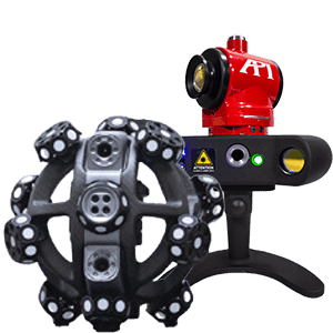
API has spent more than 30 years building and applying laser-based measurement equipment for large industrial assets. Our Radian laser tracker and on-site Real Metrologists support inspection, alignment, verification, and calibration work in energy, heavy machinery, aerospace, automotive, and manufacturing facilities around the world. Turbine work sits directly in that service lane: large geometry, limited access, tight tolerance, and a strong need for reliable data before the covers close.
Why Steam Turbine Alignment Matters During Maintenance
Steam turbines are long machine trains. The rotor, coupling, bearings, casing, diaphragm, blade rings, foundation, and generator all influence the final running condition. If one section moves, settles, grows thermally, or returns from overhaul slightly out of position, the effect compounds across the train. A small angular error at one bearing pedestal can become a measurable offset at the coupling. A casing shift can change clearances through the diaphragm path. A soft foot condition can distort the machine when final bolts are torqued.
Alignment errors usually show up as operating symptoms rather than as one obvious installation mistake. Vibration increases. Couplings see added stress. Bearing temperatures climb. Seals and packing wear unevenly. In severe cases, rotor rub or forced outage risk enters the conversation. None of those outcomes are acceptable when a plant has already committed outage time, labor, crane capacity, and OEM support to the maintenance window.
What is turbine alignment? Turbine alignment is the measurement and adjustment of the turbine-generator machine train so rotating and stationary components share the intended centerline under maintenance and operating conditions. In practice, that means checking rotor position, casing geometry, diaphragm and bore alignment, bearing pedestal location, coupling relationship, foundation movement, and thermal growth assumptions against the OEM’s required geometry.
How a Laser Tracker Measures a Steam Turbine
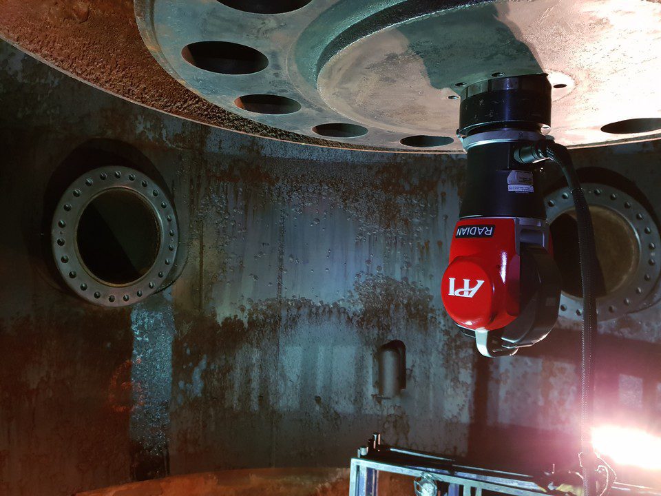
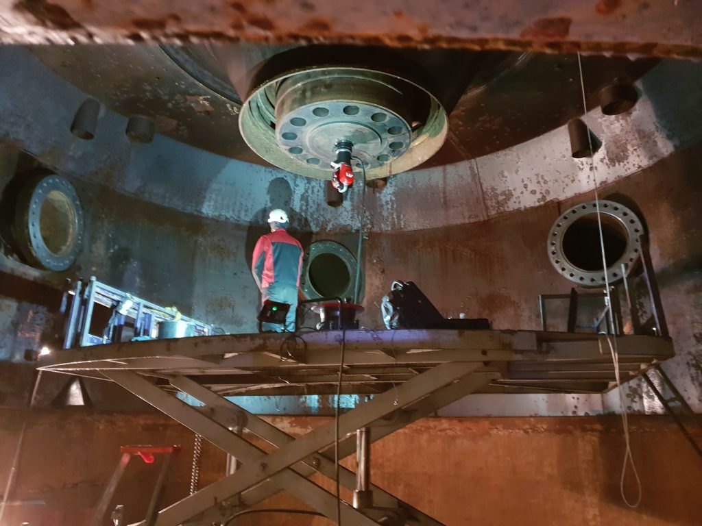
A laser tracker measures 3D points across a large working volume using a tracked target, most often a spherically mounted retroreflector or another laser tracker target. In a turbine hall, that portability is the advantage. The tracker can be placed around the machine, relocated as access changes, and tied back into a common coordinate system through stable reference points.
For steam turbine maintenance, the measurement plan usually starts with the centerline. The metrologist establishes reference geometry from bearing pedestals, casing datums, flange faces, split-line features, or OEM-defined tooling points. From there, the tracker captures the features that matter to the job: bore locations, diaphragm positions, casing faces, rotor or coupling geometry, bearing seats, generator alignment references, and foundation-related points.
The tracker does not replace judgment. It gives the team a better measurement network. A good turbine alignment job still depends on line of sight, stable targets, repeatable fixturing, temperature awareness, and an experienced metrologist who knows which points will survive the move from measurement to correction. That is where API’s on-site inspection and alignment service becomes more than equipment rental. The instrument matters, but the procedure matters just as much.
6DoF Tracking, SMRs, and Line of Sight
Line of sight is one reason a tracker works well around large rotating equipment. Instead of moving the turbine component to a fixed CMM, the measurement system moves to the turbine. A metrologist can set the tracker where it can see the features available during that stage of the outage, then preserve the coordinate network through reference targets when the tracker is repositioned.
SMRs are useful when discrete, high-accuracy points are needed on flanges, bores, pedestals, and tooling fixtures. For applications where orientation matters, 6DoF tracking can add angular information to the position data. Either way, the goal is the same: build a reliable 3D picture of where the turbine geometry actually sits, not where the drawings assume it sits.
Tops-On vs. Tops-Off Internal Alignment
Turbine access changes the job. Tops-off work gives the measurement team better access to internal features such as diaphragms, blade rings, bores, packing areas, and lower-half casing geometry. Tops-on work may be limited to external casing, pedestal, coupling, and generator-train checks. Both have value, but they answer different questions.
During major overhaul, tops-off laser tracker measurement can document the internal geometry before and after corrective work. During shorter maintenance windows, tops-on measurement can confirm external alignment, coupling position, casing movement, and foundation-related issues before they become larger problems. The best plan depends on the outage scope, access, OEM requirements, and the failure mode the plant is trying to prevent.
The Steam Turbine Alignment Procedure
Every turbine job has its own fixture set, access constraints, and OEM procedure. A fossil plant turbine-generator set is not the same as a refinery steam turbine, and neither is the same as a hydro turbine runner. The measurement logic is consistent, though. A laser tracker workflow typically follows five steps.
Step 1: Establish Centerline References
The first step is to define the coordinate system. Depending on the machine, that may come from bearing pedestals, known casing datums, split-line features, OEM centerline tooling, or existing survey monuments. The tracker setup needs stable references that can be measured again after the instrument moves or after components are adjusted.
This step is where many alignment jobs are won or lost. If the reference network is weak, every later measurement inherits that weakness. API’s metrologists treat reference setup as part of the measurement, not as a prelude to it. The goal is repeatability across the full job, including verification after correction.
Step 2: Measure Diaphragm and Bore Alignment
With the reference system established, the tracker captures internal or accessible features tied to steam path geometry. That can include diaphragm fits, bore circles, blade-ring positions, casing faces, and flange geometry. These measurements show whether the stationary components follow the intended axis and whether local deviations need to be corrected before reassembly.
For steam turbine maintenance, this is where a tracker offers a clear advantage over simpler shaft tools. A single-axis laser shaft alignment tool can help with coupling alignment. It does not describe the 3D relationship among the casing, diaphragm path, bearing pedestals, and rotor centerline. A tracker can.
Step 3: Capture Rotor and Coupling Geometry
Rotor and coupling measurements connect the internal turbine geometry to the larger machine train. Depending on access, the team may measure coupling faces, shaft-related tooling, bearing positions, generator-side references, and other features needed to understand offset and angular relationship. This is the geometry that plant teams often care about most because it is closest to vibration, bearing load, and restart risk.
Laser tracker data also helps when the correction is not obvious. A coupling may look acceptable in isolation while the casing or pedestal data shows a larger machine-train issue. The value of a 3D network is that it lets the team see those relationships instead of treating each measurement as a separate check.
Step 4: Account for Thermal Growth, Soft Foot, and Foundation Movement
Cold alignment and operating alignment are not the same thing. Steam turbines move as temperature changes. Foundation conditions, pipe strain, bolt torque, and soft foot can shift geometry between measurement and operation. That is why temperature compensation, environmental logging, and repeated verification matter during turbine work.
Laser tracker measurement gives the team a practical way to document movement. If a casing point shifts after a bolt sequence, that movement can be measured. If a pedestal changes position after correction, that change can be captured. If the OEM procedure calls for specific cold offsets to account for hot running condition, the tracker report gives the team the evidence needed to verify those offsets.
Step 5: Generate the Alignment Report
The final deliverable should not be a spreadsheet of unrelated points. For outage work, the report needs to show the reference system, measured features, deviations, recommended moves, and verification data in a format the plant, OEM, and service team can use. The report should make the correction path clear.
API’s measurement work is built around that practical handoff. The same Real Metrologists who capture the data can help interpret what the results mean for inspection, alignment, and maintenance decisions. That is especially important when the alignment report becomes part of a restart package, quality record, or OEM service file.
Laser Tracker vs. Traditional Turbine Alignment Methods
Traditional turbine alignment methods still have a place. Piano wire, optical tooling, dial indicators, reverse-indicator alignment, bore lasers, and laser shaft alignment tools all solve specific problems. The issue is scope. Steam turbine maintenance increasingly requires more than a single line, face, or coupling check. It requires a 3D understanding of the machine.
| Method | Best Use | Limitations | Where Laser Tracker Wins |
|---|---|---|---|
| Laser tracker | 3D measurement of casing, bore, diaphragm, rotor, coupling, pedestal, and generator-train geometry | Requires line of sight, stable targets, and metrology planning | Large working volume, reportable 3D data, multiple features in one coordinate network |
| Piano wire / optical tooling | Centerline checks and long straightness references | Labor intensive, sensitive to setup, limited digital output | Faster capture, richer geometry, easier verification after moves |
| Dial indicator / reverse indicator | Coupling alignment and shaft relationship checks | Local measurement only; does not describe casing or internal geometry | Connects coupling data to the broader turbine and foundation geometry |
| Bore laser / shaft alignment tool | Bore checks or coupling alignment over a defined axis | Usually limited to one axis or one machine-train question | Captures multi-axis, multi-feature geometry across the turbine hall |
The point is not that older methods are wrong. The point is that they do not always answer enough of the question. If the outage team only needs a coupling check, a laser shaft alignment tool may be appropriate. If the team needs to understand how the casing, diaphragm, rotor, bearing pedestals, coupling, and generator references relate to each other, a laser tracker is the stronger measurement method.
What a Laser Tracker Captures During a Turbine Outage
A turbine outage compresses a lot of work into a limited window. Measurement needs to support decisions quickly, but it also needs to produce defensible records. A laser tracker can help across several outage stages.
For bore and casing alignment, the tracker captures geometric relationships across large surfaces without moving the component to a lab. For diaphragm and blade-ring work, it can document positions before correction, after correction, and before final close. For rotor, coupling, and bearing pedestal geometry, it can connect local alignment readings to the full machine-train coordinate system. For foundation movement and soft foot checks, it gives the team a repeatable way to measure how the machine responds to bolt torque, loading, or correction.
That same logic applies outside steam turbines. API has supported power-generation and heavy-equipment work where the part is too large, too valuable, or too embedded in the site to move. Voith Hydro turbine work, large fabrication inspection, shipbuilding, and heavy machinery alignment all share the same metrology problem: the measurement system has to go to the asset.
When to Use a Laser Tracker Instead of a Laser Shaft Alignment Tool
Use a laser shaft alignment tool when the job is limited to coupling alignment between two accessible shafts and the machine geometry is already understood. That is a valid use case. Many maintenance teams own those tools for routine pump, motor, and small rotating equipment work.
Use a laser tracker when the job involves large geometry, internal alignment, multiple components, limited access, OEM reporting, or a need to verify the relationship between stationary and rotating features. Steam turbine maintenance often falls into that second category. The machine is too large for a simple tool-only answer, and the consequences of a wrong answer are too expensive.
The service decision is also practical. Buying a tracker, targets, software, tripods, fixtures, training, and calibration support may make sense for organizations that run continuous large-scale metrology programs. For a plant team with occasional outage measurement needs, bringing in an experienced laser tracker service team is usually faster. You get the instrument, the procedure, the metrologist, and the report without turning a maintenance job into an equipment acquisition project.
Choosing a Steam Turbine Alignment Service Partner
A turbine alignment partner should be comfortable with more than the instrument. Ask how the team establishes references, how they preserve the coordinate system after tracker moves, how they handle temperature compensation, and what the final report looks like. Ask whether they can support tops-on and tops-off measurement. Ask whether they have experience with large energy assets, not just small rotating equipment.
The right partner should also speak the language of the outage. Plant teams do not need a generic measurement vendor during a critical maintenance window. They need Real Metrologists who can work around access constraints, document data cleanly, communicate with OEM technicians, and keep the measurement plan tied to the restart decision.
API’s on-site inspection and alignment service is built for that kind of work. Our teams support measurement at the customer site, with globally local service coverage and laser-based equipment designed for large-volume industrial inspection.
FAQ
What is the most precise shaft alignment method?
For large turbine-generator sets, a laser tracker workflow is usually the most precise and complete method because it can capture 3D geometry across the machine train, not only the relationship between two shaft ends. Coupling tools can be accurate for local alignment, but they do not measure casing, diaphragm, bore, pedestal, and foundation relationships in the same coordinate network.
How long does a steam turbine alignment take?
The measurement portion can often be completed within a shift once access and references are prepared. Full outage alignment may take longer depending on tops-on or tops-off access, the number of required measurement positions, corrective moves, OEM reporting requirements, and final verification.
How accurate is a laser tracker on a turbine?
A properly planned laser tracker setup can deliver micron-level measurement data across the working volume needed for large turbine components. Real job accuracy depends on range, line of sight, temperature stability, target setup, fixturing, and the quality of the measurement network.
How often should steam turbines be aligned?
Steam turbines should be checked during major overhaul, after vibration or bearing issues, after foundation or casing work, when coupling or generator alignment changes, and whenever OEM maintenance procedures call for alignment verification. Plants with critical uptime requirements often include alignment measurement as part of planned outage scope rather than waiting for symptoms.
What are the four common alignment checks on a turbine-generator set?
The four checks most teams care about are rotor or shaft alignment, coupling alignment, casing or bore alignment, and bearing pedestal or foundation alignment. The exact list changes by OEM and outage scope, but those four categories cover most of the geometry that drives turbine running condition.
Schedule a Steam Turbine Outage Measurement
When a turbine comes apart, the measurement plan should be ready before the outage clock starts. API’s Real Metrologists can support turbine inspection, alignment, verification, and reporting with portable laser tracker measurement at your site.
Schedule a steam turbine outage measurement.