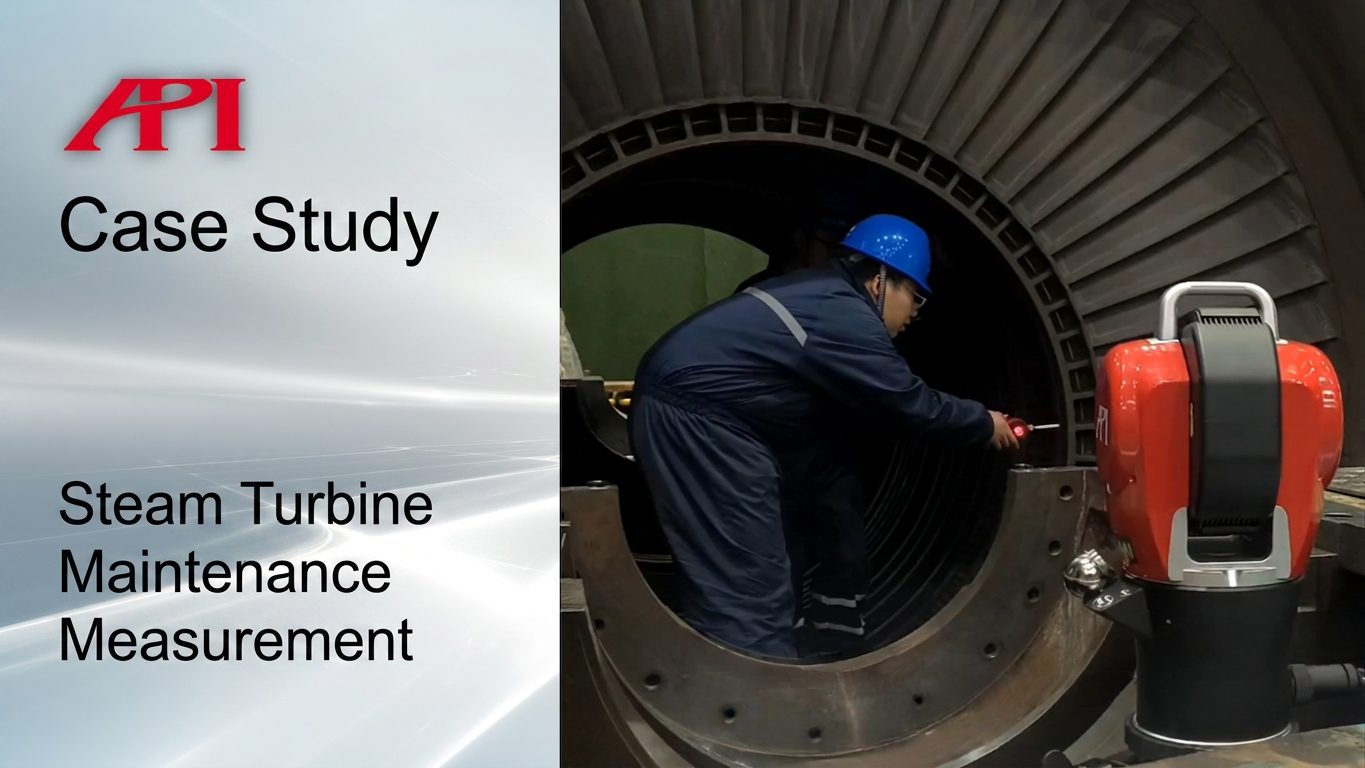
Why steam turbine overhaul measurement is so demanding
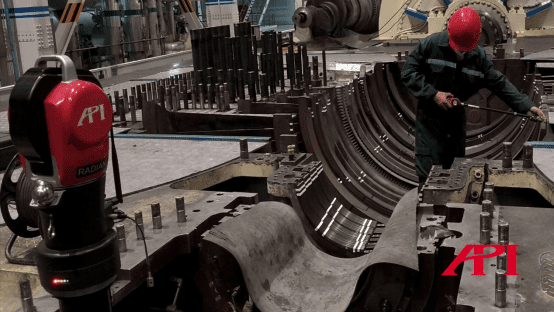
Steam turbines are large, fast, and unforgiving. During maintenance work, teams are not just checking whether parts fit back together. They are verifying whether rotor, casing, seal, and blade-related geometry still line up closely enough to protect efficiency and avoid damaging contact once the machine returns to service.
That is what makes this kind of work difficult. The machine is large, the internal geometry is crowded, and the tolerance target is tight. The source article calls for measurement accuracy around 0.05 mm, which means the inspection system has to cover a large volume without giving up precision.
Where the API Radian fits
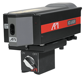
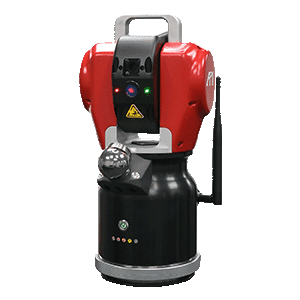
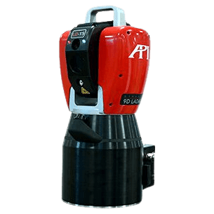
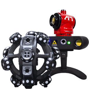
That is the use case for the API Radian laser tracker. API positions the Radian and iLT tracker families as a way to capture high-accuracy 3D data over a large working volume, then push that data straight into software for fitting, alignment, and correction decisions.
With a standard SMR, the operator touches the feature being checked while the tracker follows the target and records 3D coordinates at high speed. Once enough points are captured, the software can build cylinders, lines, planes, and other geometry, calculate deviation, and compare the measured condition against the intended fit.


The actual maintenance problem
In the example from the source article, a power plant needed overhaul measurement on a steam turbine unit after long service time. The job was to evaluate and correct the positional relationship between critical parts so the turbine could return to a safe and efficient operating state.
The measurement goal was straightforward, but not simple: bring the rotor centerline and the casing centerline into coaxial alignment, while also checking the geometry that controls how seal teeth and related components match up during operation.
That meant measuring cylindrical data from the rotor, casing, and seal-related locations, aligning everything in software, applying corrections, and remeasuring until the centerlines agreed.
How the measurement workflow was set up
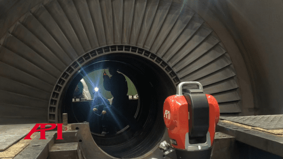
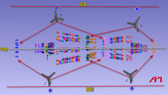
Because the turbine is both large and structurally complex, the tracker had to be positioned around the machine with multiple transfer stations. That allows the team to move the instrument between visible positions and still merge the data into one overall analysis set.

The team then established coordinate systems for the rotor and the matching casing-side features, using those frames to combine all collected data and calculate distances and offsets between corresponding locations.
Why hidden-point probing matters here
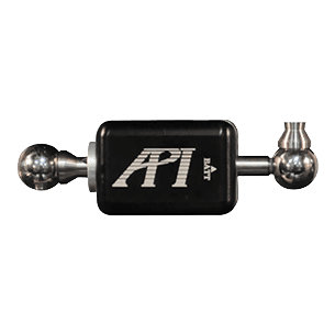
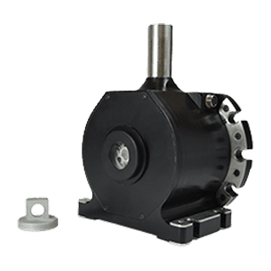
Steam turbine geometry is full of deep holes, grooves, and blocked features that are difficult or impossible to reach with a standard SMR alone. That is where the vProbe becomes important. API’s hidden-point probe gives the tracker a practical way to capture data from concealed features by letting the operator aim the receiver toward the tracker and probe the feature directly with the stylus tip.

The article notes that stylus lengths from 50 mm to 500 mm are available, which matters in overhaul work where access changes from one feature to the next. The vertical and horizontal probe orientations also make real field measurement easier than trying to force one stylus approach to fit every location.
Once the points are collected, the software aligns the full measurement set, fits the required geometry, and shows the deviation data needed to guide adjustment and remeasurement.
Why this approach works
The strength of this workflow is not just that it is accurate. It is that it gives maintenance teams one measurement path from setup, to hidden-point capture, to software alignment, to final correction. For large rotating equipment where fit, clearance, and coaxial alignment all matter, that is a much more practical way to support overhaul work than treating each check as a separate disconnected measurement task.
For more information on steam turbine maintenance measurement, contact an API metrologist today.