
Why Fixture Inspection Is a Production Problem
In high-volume automotive production, fixtures and tooling do more than hold parts in place. They set the geometry that determines fit-up, gap and flush, and ultimately whether downstream assembly is smooth or full of rework. When a fixture drifts out of spec, quality issues show up fast.
The challenge is that many traditional inspection workflows are not friendly to production reality. Moving a large fixture or subassembly to a CMM lab adds handling risk and takes time. Portable arms are easier to bring to the line, but they can be limited by reach, repositioning, and operator technique when the work volume is large.
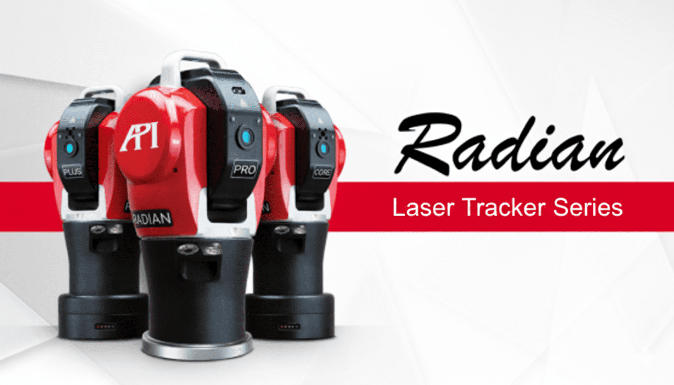
Why the Radian Fits This Kind of Work
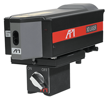
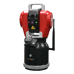
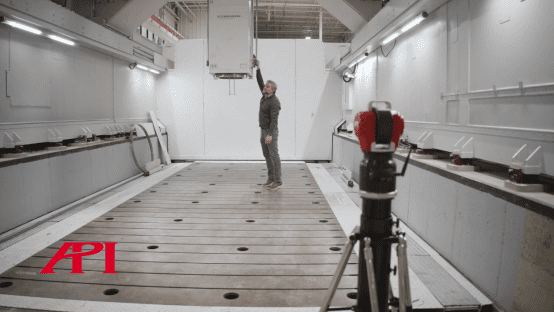
This is exactly the kind of job where the API Radian laser tracker makes the workflow simpler. A tracker can be set up near the workpiece, tied into a common coordinate system, and used to capture 3D points quickly with high accuracy over a large working volume. Just as important, it supports live coordinate feedback, which turns fixture adjustment into a guided process instead of a trial-and-check loop.
The Job: Verify Locating Pins and Guide Adjustment
In this case study, the team used a Radian laser tracker to inspect an automotive final-assembly fixture. The measurement goals were straightforward but demanding:
1. Check locating-pin position accuracy to better than 0.1 mm. 2. Compare measured results to CAD and guide real-time adjustment.
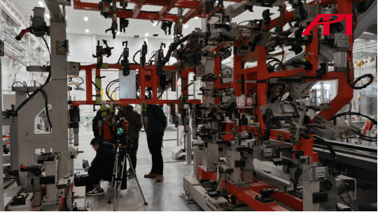
How the Measurement Setup Worked
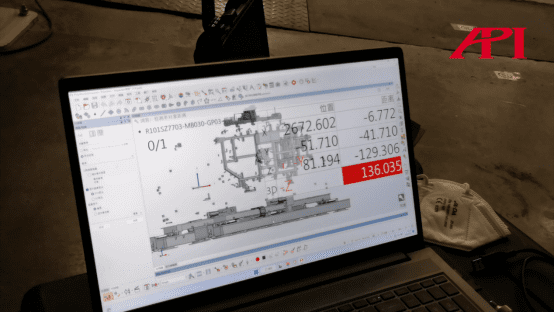
The tracker was placed at a convenient position around the fixture and connected to a laptop running the measurement software.
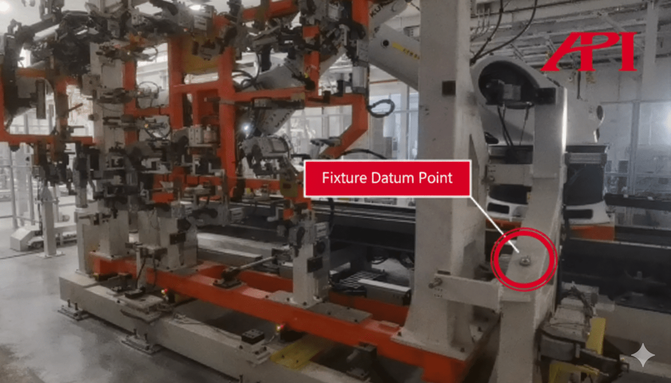
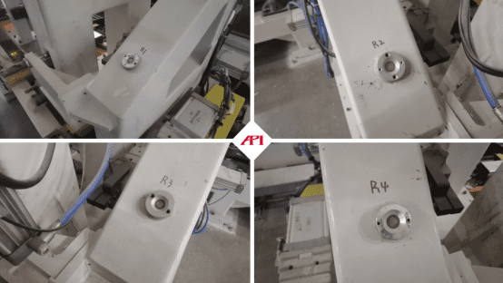
To align everything to a shared coordinate system, the operator first measured four reference points on the fixture. Once the coordinate system was established, the CAD model was imported, and point checks could be taken directly against nominal geometry.
Capturing Points and Building the Inspection
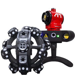
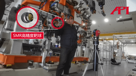
Using an SMR target sphere, the operator touched required points on the tooling and captured 3D coordinates directly into the software. From the measured points, the software can build lines and planes, evaluate deviations against CAD, and generate an inspection report.
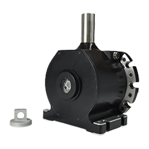
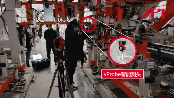
Measuring Hidden Points with vProbe
Fixtures often include deep holes or occluded features that are hard to access with a standard target. For those points, the workflow used a vProbe accessory designed for hidden-point measurement.
Real-Time Adjustment with Coordinate Guidance
Instead of measuring, adjusting by feel, and rechecking later, the tracker workflow provides coordinate guidance in real time. As the fixture is adjusted, the operator can see coordinates update live and move the tooling into the intended position more efficiently.
The Takeaway
For fixture inspection and adjustment, the value is not just precision. It is a workflow that fits the line: fast setup, consistent point capture, and practical real-time feedback against CAD. In this application, the Radian laser tracker provided a direct way to verify locating-pin positions and guide adjustment without the overhead of moving the tooling to a lab environment.
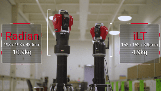
Other Options in the Tracker Lineup
Alongside the Radian series, API also offers the iLT laser tracker for teams that prioritize portability and fully wireless operation.
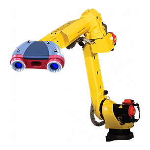
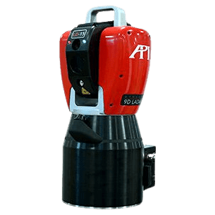
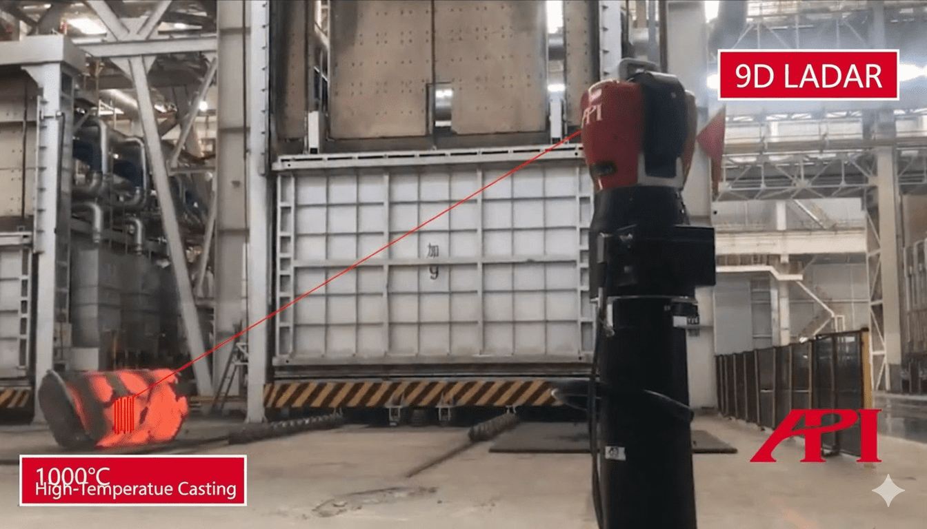
For non-contact applications, API also offers 9D LADAR systems capable of fast point-cloud capture for inspection workflows.
For more information on automotive tooling inspection and adjustment, contact an API metrologist today.