
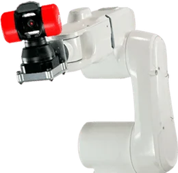
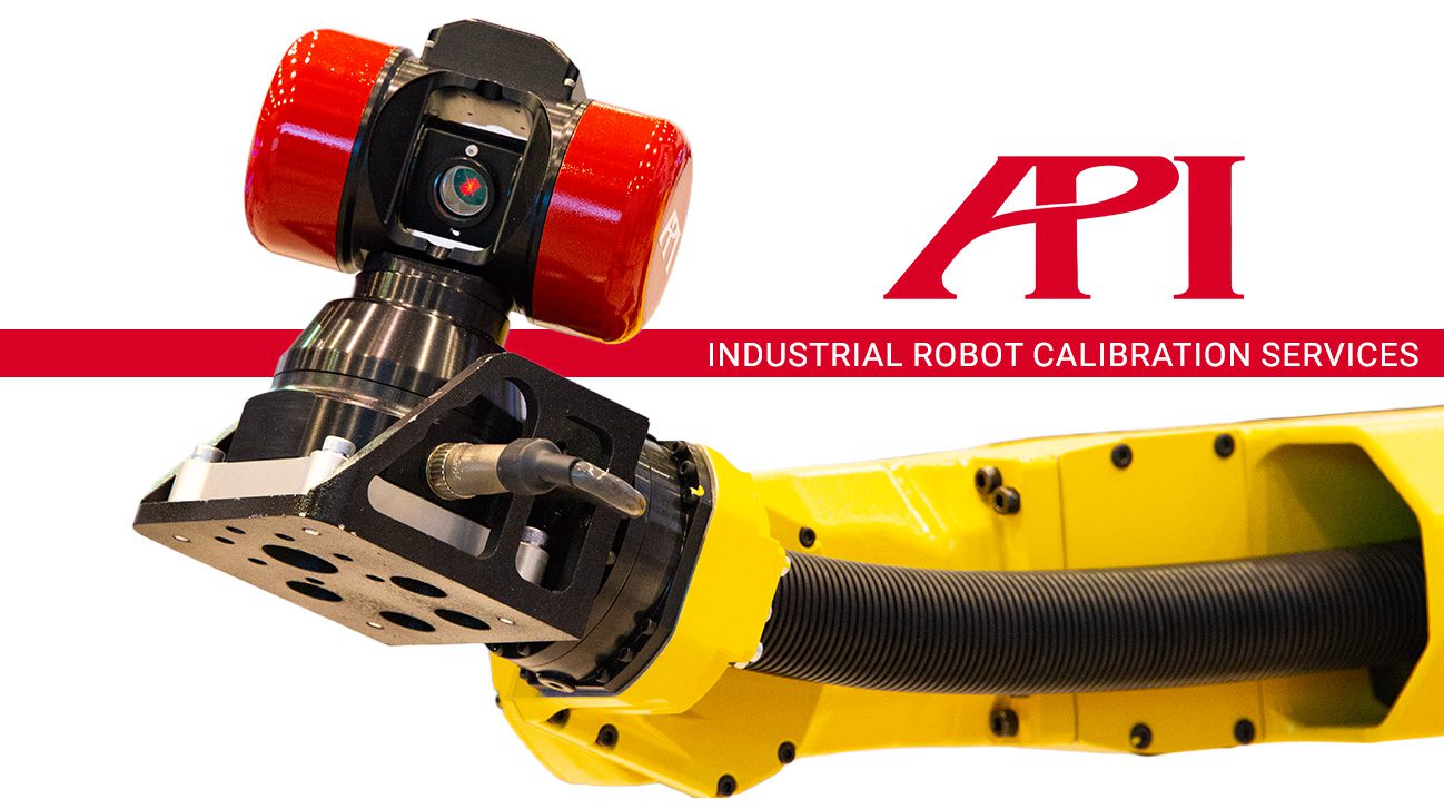
If a new robot rolls off the crate at ±0.05 mm repeatability and ±1.5 mm accuracy, the factory spec sheet is not lying. Three years later, that same robot may be drilling holes in a wing spar or laying beads on an EV battery tray. It often cannot hold ±0.5 mm. The arm still returns to the same spot every cycle. It just returns to the wrong spot.
Robot calibration is how you find out by how much, and how you fix it without taking the cell apart.
This guide is for manufacturing engineers, quality managers, and plant supervisors who already own industrial robots. It is for teams watching accuracy problems show up in rework rates, FAI failures, or programs that used to hit tolerance. We have run on-site laser tracker measurements for 30 years. Robot calibration is one of the jobs we do most often. What follows is the field procedure, the standards behind it, and what to expect when a service team arrives.
Why industrial robots lose accuracy over time
Every industrial robot ships with a factory kinematic model. That model is the math the controller uses to turn a Cartesian target into joint angles. Its accuracy starts to decay the moment the robot leaves the factory. Four sources do most of the damage.
Kinematic error: joint and link geometry drift
The controller’s kinematic model assumes joint offsets, link lengths, and rotation axes for a nominal arm. Real arms are never quite nominal. Encoder reference points shift after a gearbox replacement or a hard stop collision. Harmonic drives develop backlash. A link can subtly bend after a multi-ton forklift brushes past the base. Each error is small. One joint might be off by a few hundredths of a degree, or one link by a tenth of a millimeter. The errors compound through the kinematic chain. By the time you reach the wrist, a 0.05° error at the shoulder becomes a 1 mm error at the TCP.
Thermal expansion in production environments
Shop floors are not 20°C ± 1°C. A welding cell running at 40°C can change measurably as a cold robot warms up. Steel arms expand about 12 µm per meter per °C. Across a 2 m reach and a 30°C temperature change, that is almost a millimeter of drift. That happens before any other error is counted. Robots in paint booths, plastic molding cells, and foundry work see even larger swings.
Payload sag and wrist wear in high-cycle applications
A 50 kg payload on the flange loads the wrist gearboxes and the outer links in ways the factory acceptance test never saw. After a million cycles, the wrist develops measurable play. Drill effectors, spindle attachments, and heavy grippers accelerate the problem. The robot is still repeatable. It returns to the same wrong position every time, which is why the controller does not know anything is wrong.
Robot accuracy vs. repeatability: the distinction that matters for production
This is the single most common source of confusion on the shop floor, and it matters more now than it used to.
Repeatability is how tightly the robot returns to the same point when commanded to the same point. Accuracy is how close that point is to where the CAD program says it should be. A robot can have excellent repeatability (±0.05 mm) and poor accuracy (±2 mm) at the same time. In fact, most do.
The reason it used to not matter: teach-and-play programming. An operator jogged the robot to each target, recorded the pose, and the robot replayed those taught positions. Since the robot commanded itself back to its own recorded position, only repeatability mattered.
The reason it matters now: offline programming. A process engineer may generate a 4,000-pose welding program from CAD in simulation software. When that program goes to the robot, every target is a calculated Cartesian position. The robot has to actually go there, not to a taught point. If the kinematic model is off, the program is off by the same amount everywhere. That is the problem calibration fixes.
ISO 9283: the standard for robot performance testing
ISO 9283 is the international standard for measuring and reporting industrial robot performance. It defines the tests, test conditions, pose set, and metrics you get back. Those metrics include pose accuracy (AP), pose repeatability (RP), distance accuracy (AD), path accuracy (AT), and drift over time (dAP).
An ISO 9283 test is not the same thing as a calibration. The test tells you what the robot is doing now. A calibration changes the robot’s kinematic parameters so its behavior matches the commanded behavior. Most serious calibration jobs include an ISO 9283 performance test as before-and-after evidence. The first run establishes the baseline. Calibration corrects the model. The second run proves the improvement with a standards-referenced number.
Aerospace and defense customers increasingly require ISO 9283 test reports for cell qualification and supplier audits. If you deliver parts to a Tier 1 automotive supplier or a prime contractor in 2026, ISO 9283 documentation matters. ISO 17025 accredited calibration services are becoming table stakes, not a differentiator.
API Metrology supports all 14 tests in ISO 9283.
How laser tracker-based robot calibration works
A laser tracker is the standard instrument for industrial robot calibration. It can capture the robot’s true TCP position and orientation across a large working volume. That volume is large enough to characterize the full arm envelope, with enough accuracy to separate kinematic error from measurement noise.
The procedure is the same in principle across robot brands. The details change depending on the controller.
Setting up the measurement field
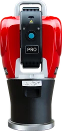
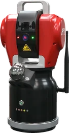
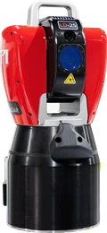
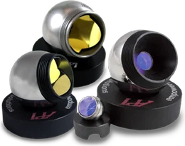
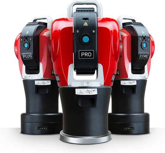
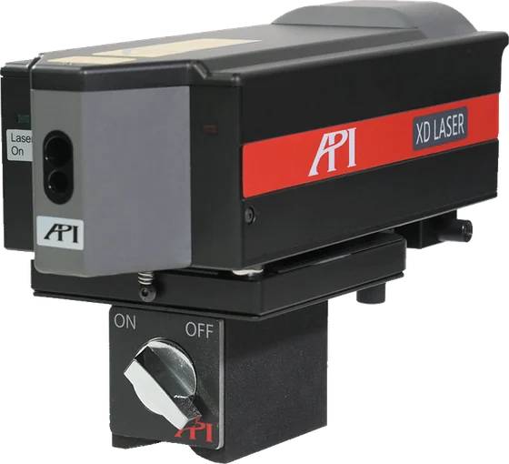
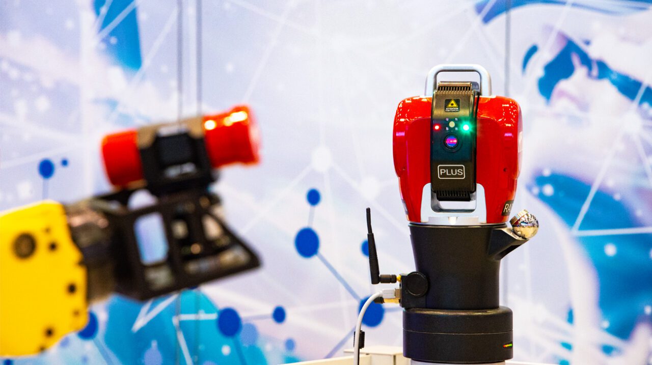
We position the Radian laser tracker outside the robot’s working envelope. It usually sits on a heavy tripod about 2 to 4 meters from the flange. A spherically mounted retroreflector (SMR) or a Smart Track 6DoF sensor mounts to the robot wrist. The choice depends on whether we need TCP position only or full 6 degrees of freedom. The tracker establishes a coordinate frame and the robot world. The software then links the tracker’s coordinate system to the robot’s base frame through reference points.
Environmental temperature is logged. A cold robot is not the same arm as a warm one. The kinematic model needs to match the conditions the robot will run in. For production-floor calibration, we let the robot warm up to operating temperature first.
Running the kinematic characterization routine
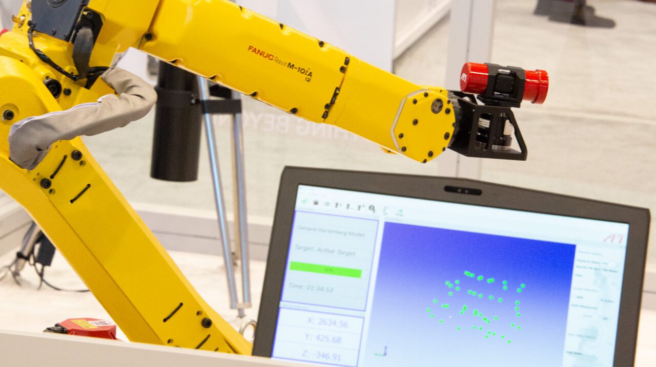
The robot cycles through a pre-planned set of poses. A typical run uses 30 to 100 poses, depending on how many parameters the controller exposes. The poses exercise every joint across its usable range. They also place the TCP at different orientations in different workspace volumes. The laser tracker captures the actual TCP position at each pose. With a 6DoF sensor, it captures orientation too.
A numerical solver then fits a kinematic model to the measured data. It adjusts joint offsets, link lengths, DH parameters, and axis misalignments. The goal is to make the modeled TCP positions match the measured positions as closely as possible. The residual error tells us how well the model fits. Good solves land in the 30 to 80 µm range after fitting.
Updating parameters in the robot controller
Different manufacturers handle parameter updates differently. Some controllers expose a calibration table that can be overwritten directly. Others require a compensation file at program execution. Some integrate with offline programming packages such as RoboDK, Delmia, and Process Simulate through vendor-specific APIs. We document the old and new parameters and archive both, along with PPE(Path Planning and Enhancement). We compensate already existing offline paths and generate new paths for the customers. . That way, the calibration can be rolled back if a production issue surfaces later.
Verification measurement: before and after accuracy numbers
A second measurement run captures post-calibration performance, ideally following the ISO 9283 test cube. The report gives you pose accuracy before and after, both per axis and volumetric. It also includes a drift test if the cell runs long cycles. That number, signed by an ISO 17025 accredited metrologist, goes into your cell qualification package.
What to expect from an API robot calibration service visit
Every site visit is scoped to the cell. We do not sell a “generic robot calibration” package. Robot calibration on a clean-room assembly line is not the same job as calibration on a 1,200-amp MIG welding station. That said, the rhythm of the visit is fairly consistent.
What to prepare before the team arrives
A pre-visit checklist goes out 2 weeks ahead. The high-value items are straightforward:
- Confirm robot make, model, and controller firmware version.
- Schedule the cell offline for the calibration window. Budget half a shift per robot for a standard job.
- Clear a working perimeter around the robot so the tracker can see the flange from multiple positions.
- Make the process engineer and controls engineer available for the parameter update step.
If the robot has a collision history or a recent gearbox replacement, we want the service records.
Typical timeline and deliverables
For a single-robot calibration, plan for half a day to a full shift on-site. Multi-robot cells scale roughly linearly. A 4-robot welding cell is a 2-to-3-day engagement. The added time comes from cell-level coordinate alignment and inter-robot relative accuracy checks. Deliverables include a written calibration report with before-and-after ISO 9283 numbers. You also get the updated parameter file, the archived previous version, and a verification sheet traceable to our A2LA-accredited lab.
Works with Fanuc, KUKA, ABB, Yaskawa Motoman, and Kawasaki
The measurement side is OEM-agnostic. A laser tracker does not care which controller is driving the joints. The parameter-update side is OEM-specific, and we maintain working toolchains for the major brands. If you run a KUKA welding arm or a Yaskawa Motoman in an EV battery line, we have done the calibration before.
When to calibrate: frequency, triggers, and red flags
Most production robots benefit from an annual calibration cycle. Beyond the annual check, a few triggers should pull a calibration forward. Any crash or collision can shift the kinematic model enough to drop the arm from tolerance. That includes low-energy impacts. A gearbox, encoder, or motor replacement resets the reference points the controller thinks it knows. Switching a cell from teach-and-play to offline programming is another red flag. Offline programming exposes accuracy problems that taught programs never did.
Watch for creeping scrap rates on parts that used to pass FAI. Drill entry points or weld bead positions that need manual touch-up are another warning sign. So are tool-change sequences that no longer dock cleanly. Those are usually accuracy problems, not programming problems. An inspection and alignment pass with a laser tracker finds them in a few hours.
Industries we serve
Robot calibration shows up across manufacturing, but three sectors generate most of the jobs we run.
Automotive: body-in-white and EV battery assembly
Weld cells, stud welding robots, and adhesive dispensing arms in body-in-white rely on sub-millimeter accuracy to hit stack-up tolerances. EV battery tray and module assembly runs tighter tolerances than traditional BIW. ±0.2 mm is not unusual, and calibrated robots help the line run reliably. Our automotive metrology solutions often start with a calibration service and grow into a recurring measurement program.
Aerospace: drilling, fastening, and composite layup robots
Robotic drilling and fastening of wing skins, fuselage panels, and spar assemblies lives or dies by positional accuracy. Automated fiber placement and composite tape layup robots need repeatable Cartesian paths across large envelopes. For aerospace measurement services, calibration is usually paired with tool-stand and jig verification in the same visit. A calibrated robot still produces bad parts if it works against an uncalibrated fixture.
Heavy manufacturing and general industrial
Heavy equipment welding, agricultural machinery assembly, and general industrial robotics are hard on robot cells. These robots cycle often and sit in environments that are hot, dirty, or both. The work is usually triggered by a specific problem, not a calendar date. Common triggers include a customer return, a failed first article, or a retooling. The calibration work is the same, but the site conditions are less controlled.
The API Robot Metrology Solution (RMS)
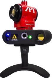
The Robot Metrology Solution is the integrated package we bring on-site for robot calibration and cell qualification work. At its core are two instruments working together: the Radian laser tracker and the Smart Track Sensor (STS).
Radian and Smart Track hardware
Smart Track is our automated 6DoF sensor. It mounts directly to the robot flange and locks onto the Radian’s laser beam. The sensor streams real-time position (x, y, z) and angular orientation (pitch, yaw, roll) back to the software. The physical specs are tuned for shop-floor work. Smart Track weighs 1.4 kg and measures roughly 5 × 8 × 2 inches. It has M6 mounting holes, an operating radius of more than 50 meters, and angular tracking speeds up to 50°/sec. That lets the sensor keep up with a robot running at production pace. Pitch articulation covers ±55°, roll ±60°, and yaw is effectively infinite at ±180°. Angular accuracy is 0.005°, which translates to ±12.5 µm of measurement uncertainty at the sensor.
Dynamic 6DoF data
What that means in practice: the STS paired with an API Laser Tracker can capture true 6DoF TCP data while the robot moves at real cycle speeds. That separates a full kinematic calibration from a static pose-by-pose check. The same sensor also supports dynamic accuracy characterization, adaptive feedback control, and volumetric robotic compensation. We use it for large assembly guidance, robotic calibration, kinematic modeling, DH modeling, quality measurement, and 6D adaptive feedback control.
RMS is deployed by our team of Real Metrologists, on-site at your facility. We are Globally-Local, with offices on every major continent. The service team that shows up is local and on-call. Schedule a robot calibration and we will scope the cell, prep the checklist, and put a metrologist on your floor.
FAQ: industrial robot calibration
How accurate are industrial robots?
Modern industrial robots have excellent repeatability, typically ±0.03 to ±0.1 mm. Their absolute positioning accuracy is often an order of magnitude worse, commonly ±0.5 to ±2 mm out of the box. Repeatability is how tightly the robot returns to the same commanded point. Accuracy is how close that point is to where the CAD program says it should be. Most uncalibrated robots are repeatable but not accurate. That becomes a problem when you switch from teach-and-play programming to offline programming.
What causes industrial robot inaccuracy?
Four sources account for most of it. Kinematic error includes joint encoder offsets and link-length drift. Thermal expansion affects the base, arm, and wrist as production heat rises. High-cycle applications add payload-induced wrist sag and gearbox backlash. Collision or crash events can also shift end-effector geometry. All four accumulate over time and push the robot’s true TCP away from where the controller thinks it is.
How long does robot calibration take?
A single-robot calibration typically takes half a day to a full shift on-site. That includes measurement field setup, a 30-to-100-pose characterization run, controller parameter update, and verification measurements. Four-to-eight-robot cells usually run two to three days. Per-robot downtime is often under four hours if the cell is prepped before the team arrives.
What is ISO 9283 robot testing?
ISO 9283 is the international standard that defines how industrial robot performance is measured and reported. It specifies tests for pose accuracy, pose repeatability, distance accuracy, path accuracy, and drift. Measurements use a defined test cube and a 3D measurement system such as a laser tracker. The result is a spec-comparable number for how accurate the robot actually is.
How is a laser tracker used to calibrate a robot?
A laser tracker measures the robot’s tool center point in 3D space while the robot moves through commanded poses. A 6DoF sensor like the Smart Track mounts to the robot flange and gives both position and orientation. Software compares measured poses to commanded poses. It then solves for the real kinematic parameters, including joint offsets, link lengths, and DH table corrections. The corrected parameters are written back to the controller. A verification run then confirms the accuracy improvement.
What is TCP calibration on a robot?
TCP calibration establishes the exact position and orientation of the tool relative to the robot’s flange. TCP stands for tool center point. Without an accurate TCP, any programmed path will be offset by the tool-mounting error. TCP calibration is separate from full kinematic calibration of the robot itself, and it should follow that work.
How often should industrial robots be serviced?
Most high-accuracy industrial robots should be calibrated every 12 months. You should also calibrate after any collision, gearbox replacement, or encoder replacement. A new offline program that assumes factory-fresh accuracy is another trigger. So is production data that shows creeping rework or scrap. Welding and assembly robots running 24/7 in hot cells often need more frequent checks. Every six months is common.
Can our team do this in-house?
Some plants run their own robot health checks. If you have a calibrated laser tracker, trained metrologists, and familiarity with your controller’s parameter-update interface, an in-house program can work. If any of those is missing, bringing in a service team usually has the better ROI. We also run metrology training for facilities that want to eventually bring the work in-house.
Ready to schedule a robot calibration?
If robot accuracy is showing up in scrap data, FAI rates, or a cell that will not hold its program, we can be on-site with a Radian, a Smart Track, and an ISO 9283 test plan. Schedule your robot calibration today, or talk to a metrologist about the specifics of your cell.